
Capacitor switching
Capacitor banks and systems are designed with switching mechanisms to connect and disconnect them from the system as needed, often several times a day. Switching a capacitor bank is different from switching a normal load. In a capacitive load, the current waveform leads the voltage by 90°.
[1] A capacitor, at the time of switching on, offers a temporary short-circuit like condition to the supply terminals, causing a heavy current inrush. Further, sudden voltage fluctuation and transient conditions also give rise to heavy current surges in the capacitor.
If the switch contacts close at the moment of zero voltage, a sudden current surge will follow, overshooting the maximum peak value. The peak current inrush magnitude is a function of the rated capacitor current and the strength of the system to which the capacitor is connected, limited by the available short-circuit current of the system.
The voltage and current waveforms oscillate at a frequency much higher than the power system frequency. After a short period of time, the waveforms settle down to their steady-state values. Figure shows the resultant waveforms under switching conditions.
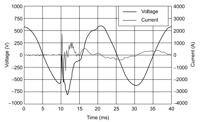
Line current and voltage waveform during switching in a capacitor.
[2] Switching off a capacitive load poses even more challenges, if the current is interrupted very close to its zero crossing when the voltage is at its peak value. As the switch contacts open, the charge (corresponding to the voltage at separation) trapped in the capacitor cannot be neutralized instantly.
As the contacts continue to separate – a process that lasts about three electrical cycles – the dielectric strength of the gap between them increases in a near linear fashion, but the voltage difference across the contacts, (i.e. between the sinusoidal system voltage and the constant capacitor voltage) increases faster.
The voltage across the parting contacts may exceed the dielectric strength of the gap between the contacts, causing an insulation breakdown, and resulting in an arc that re-establishes current flow. This re-strike of current flow may occur after a quarter of a cycle of initial interruption.
When the current is re-established, it becomes a high-frequency, exponentially decaying sinusoidal wave. The high-frequency oscillations give rise to high-frequency voltage fluctuations, similar to that of the capacitor switching on. Resistance present in the system quickly damps these oscillations.
At the next current zero, the arc will be interrupted again, but this time the contacts will be farther apart than during the first interruption, thereby providing a greater dielectric strength between the parting contacts.
At the second interruption, the dielectric strength between the parting contacts, which are still at less than half of their ultimate separation distance, may slightly exceed the voltage difference across the opening contacts. This will allow a successful current interruption.
A typical voltage waveform during capacitor disconnection is given in Fig (Current waveform is current flowing into capacitor bank being energized.) In some cases, a second re-strike may occur at this point, and successful interruption may take place at the third current zero.
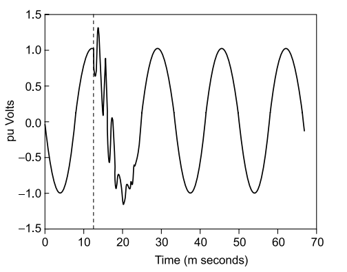
Secondary bus voltage waveforms during utility capacitor switching.
Capacitor banks applied within distribution substations typically consist of one to four banks of switched capacitors. The switched banks are designed to come on and off automatically based on power factor, VARs, and/or voltage.
Due to load variations, a number of switching operations will occur daily. Each switching event is followed by a low-frequency decaying ring wave transient that can result in power quality problems for nearby industrial and commercial loads.
A typical power factor correction system is shown in Fig, with three capacitor banks of 1.5 MVAR each, along with their series reactors and individual switches.
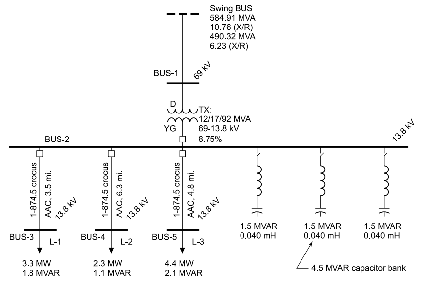
Typical utility substation showing capacitor banks and adjacent distribution loads.
Single bank switching transient
Figure (a) shows the voltage transient that will occur for the closing of the first 1500 KVAR capacitor step , while no other steps are energized. Due to switch variations, and possible pre-strike conditions, phase A and phase B vacuum switches are assumed to close prior to the phase C switch.
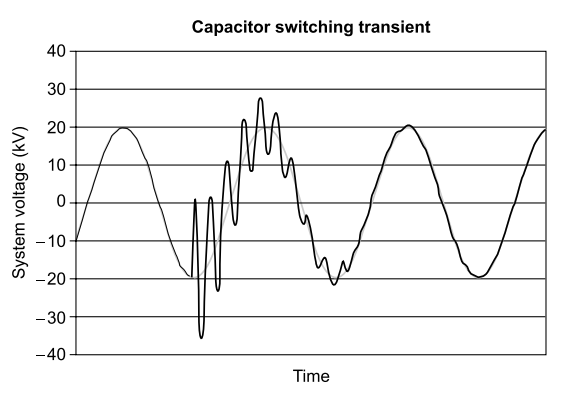
(a) Capacitor switching transient.
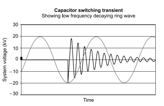
(b) Decaying ring wave.
For an ungrounded bank, the first phase switch to close will result in no current flow or voltage transient. The neutral voltage will then follow the phase voltage, and phase-to-phase voltage will be impressed across the remaining two switches. Upon closure of a second contact, a transient such as the one shown in Fig. (b) will occur.
The worst-case transient will occur when the second switch closes near the peak of the phase-to-phase voltage waveform. Switches will begin to conduct near peak voltage due to pre-strike.
The transient is actually composed of a decaying ring-wave transient superimposed on the voltage waveform as shown in Fig.(b). The duration of the decaying ring-wave transient is dependent on the system X/R ratio at the capacitor bank. High X/R ratios will result in long durations, while low X/R ratios will result in short duration transients.
In examining the transient waveforms the following statements can be made in regard to single capacitor bank switching.
- On closing of the second contact (for an ungrounded bank), the line-to-line system voltage will be pulled to near zero volts. This is called voltage depression.
- Immediately following the voltage depression, the system voltage will attempt to recover, but will over-shoot the normal system voltage by an amount that is nearly equal to the voltage dip. Theoretically, two per-unit over-voltages can occur due to capacitor switching.
- The frequency of the capacitor transient is equal to the system’s natural frequency. Therefore, large capacitor banks will result in lower frequency decaying ring-wave transients, while small banks will result in higher frequency ring-wave transients.
- The duration of the ring-wave transient is dependent upon the system X/R ratio at the capacitor bank. Systems with higher X/R ratios result in longer duration transients.
- Transients associated with substation capacitor banks can last as long as 30 to 40 cycles.
Multiple capacitor bank switching
Multiple capacitor bank switching transients occur when a capacitor bank is energized in close proximity to a capacitor bank that is already energized. Such a switching operation is common in multi-step automatic capacitor banks, as shown in Fig Upon energization of the uncharged bank, the adjacent charged bank dumps a high-frequency high-magnitude current into the uncharged bank.
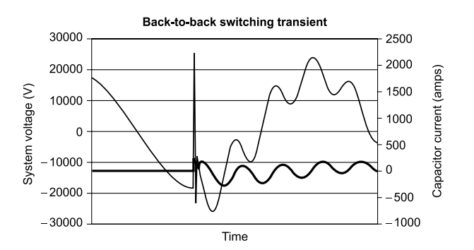
Voltage and current waveform associated with back-to-back capacitor bank switching.
This high-frequency high-magnitude current is limited by the impedance between the capacitor stages (resistance and reactance of bus work, fuses, vacuum switches, etc.). Most banks have to be supplemented with transient inrush reactors to reduce the magnitude of the transients to within the vacuum switch and fuse ratings. The high magnitude current is not seen by the power system as it occurs between the parallel banks.
The following should be noted in regards to back-to-back capacitor bank switching:
- The system voltage still experiences a low frequency decaying ring-wave transient.
- The voltage depression is not to zero volts, as was the case for single capacitor bank switching transients.
- The system voltage over-shoot is reduced to an amount equal to the voltage depression.
- Multiple zero-crossings are still possible.
In purchasing and specifying capacitor banks and harmonic filter banks, the cost associated with nearby electrical equipment malfunction or damage should be evaluated against the cost of additional equipment to eliminate switching transients.
Capacitor banks and harmonic filter banks in the 2.4 kV through 34.5 kV voltage range can be equipped with zero voltage closing controls to nearly eliminate switching transients. These controls operate their associated vacuum switches so that contact closure occurs at the zero-voltage crossing point.
Power quality concerns
Capacitor bank energizing transients are becoming increasingly more important with the growing number of capacitor bank installations in power systems.
This is because capacitor bank switching is one of the most frequent utility operations, potentially occurring multiple times per day and hundreds of time per year throughout the system, depending on the need for system voltage/VAR support from the banks.
There are a number of important concerns when capacitor banks are applied at the transmission system voltage level, like transient-related currents and voltage transients at the capacitor bank substation and neigh-bouring substations.
These may include:
- Phase-to-ground over-voltages, phase-to-phase over-voltages and over-voltages due to voltage magnification (i.e. exciting system resonances or dynamic over-voltages).
- Power quality impact on sensitive customer loads due to variations in voltage when energizing capacitor banks.
- This may also involve voltage magnification phenomena if there are capacitor banks on
- the lower voltage system in the vicinity of the switched banks.
- Capacitor bank energization inrush currents.
- Capacitor bank outrush currents due to faults in the vicinity of capacitor banks.
These transient voltages and currents can have an impact on equipment design and protection.In general, some of the equipment-specific design and protection issues include:
- Phase-to-ground and phase-to-phase insulation switching withstand to voltage stresses.
- Controlled closing for circuit breakers (pre-insertion resistors/reactors or synchronous switching).
- Capacitor bank and substation circuit breakers ANSI/IEEE C37 requirements.
- Current limiting reactor requirements.
- Surge arrester energy requirements (including capacitor bank circuit breaker re-strike events).
- Secondary metering and control issues (usually associated with high-frequency inrush currents).
- Voltages appearing on a power system associated with utility capacitor bank installations.
There are three power quality concerns associated with single capacitor bank switching transients. These concerns are most easily seen in Fig, and are as follows:
- The initial voltage depression results in a loss of voltage of magnitude ‘D’ and duration ‘T1’.
- The recovering system voltage will result in an initial transient over-voltage of magnitude ‘S’ and duration ‘T2’.
- Multiple zero-crossings. For the transient in Fig, a total of three zero crossings occur before the natural system voltage zero crossing.
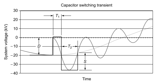
Height, depth, and time of voltage dip and spike shown on transient waveform.
Utility capacitor bank switching
Utility capacitor bank switching can have negative impacts on power quality – especially for customer power systems. AC and DC drives, along with other electronic equipment, can be very sensitive to transient voltages.
Utility capacitor bank switching transients can be magnified at low voltage capacitor locations on customer power systems, causing drives to trip, and production and other processes to stop. At a time when customers are being allowed to choose their power provider, utilities cannot afford to be seen as the cause of customer power problems.
Studying, analyzing, and preventing utility capacitor bank switching events often requires the use of sophisticated computer simulation tools. Simulations provide a convenient way to characterize transient events, determine resulting power quality problems, and evaluate possible solutions.
Frequently, simulations are performed in conjunction with power system monitoring for verification of models and identification of important power quality concerns.
Application considerations include capacitor bank configurations, insulation withstand levels, switchgear capabilities, grounding, over-current protection, over-voltage protection, energy duties of protective devices, and unbalance detection.
There are a number of important transient-related concerns when transmission voltage level capacitor banks are applied. Transmission system concerns include insulation withstand level, switchgear capabilities, energy duties of protective devices, and system harmonic considerations. These considerations must also include distribution systems and customer facilities.
Analytical methods provide the framework for evaluating a variety of power quality phenomena, including the impact of utility capacitor bank switching on the customer system. Typically, a model of the customer system and relevant parts of the utility system is developed to conduct transient switching surge analysis. This model can be used for simulations to predict power quality problems and evaluate possible solutions.
Analysis results include recommendations for the possible mitigation of switching problems. Analysis of various methods for controlling transient over-voltages is based on economic, control and technical considerations. Primary concerns generally evaluated for a capacitor bank application study include, apart from factors mentioned above:
- Transient over-current and over-voltage magnitudes for normal capacitor bank energizing operations.
- Various transient control methods (e.g. synchronous closing, pre-insertion inductors/ resistors).
- Arrester duties for voltage magnification conditions, and during capacitor bank re-strike events.
- Phase-to-phase transients at transformer terminations.
- System frequency response characteristics (resonance).
- Ferroresonance possibilities.
- Impact of capacitor bank switching transients on customer systems.
Recommendations can then be made on the following aspects:
- Requirements for capacitor bank switching devices, including the effectiveness of pre-insertion transient limiting devices and synchronous closing control for mitigating transient over-voltages and over-currents during switching.
- Deployment of current limiting reactors for reducing both inrush and outrush currents.
- Arresters to protect against excessive transients during capacitor bank switch re-strike events.
- Protection against excessive transients at lower voltage capacitor banks, including capacitor bank switching controls or surge arresters.
- Protection against excessive transients and nuisance tripping of adjustable-speed drives at customer locations, including capacitor bank switching controls or reactors.
- Guidelines for capacitor bank design with respect to over-voltage mitigation, reactor requirements and arrester applications.
Other adverse factors for switching
(1) In metallized shunt capacitors, inrush current surges during switching cause large current densities to occur at the metallized edges and also on the metallized electrode surface of capacitor elements.
When a capacitor is switched on and connected to supply while other capacitors are already connected, this new capacitor offers a momentary short-circuit condition for all these capacitors (and the supply), and they get momentarily discharged through the new unit.
Metallized capacitors have a tendency to self-heal under conditions of such high current transients, and hence the capacitance value and correspondingly KVAR output goes down with time. This factor is predominant for fluctuating loads like sugar factories, rolling mills, drawing units, cable industry etc.
On account of these factors, non-metallized power factor correction capacitors are
preferred, being extremely stable and reliable, whenever frequent switching of capacitors
like those in capacitor banks and automatic power factor correction (APFC) panels are
involved.
A capacitor bank consists of a number of capacitors connected in parallel to each other. These capacitor banks may be made partially ON and OFF depending upon load conditions, in such a way as to maintain the required power factor.
(2) Development of semiconductor technology had adverse impact on the alternating current network. The sinusoidal waveform gets distorted by consumption of the reactive energy with the non-sinusoidal pattern of currents.
Distortion can be expressed by the content of higher harmonics. The content of harmonics results in increase of capacitor current, since its impedance decreases with increasing frequency.
This may cause damage to the capacitor, unsatisfactory tripping of circuit breakers and incorrect operation of the end equipment.
This situation can be resolved by installation of capacitors with reactors (detuned PF correction), which attenuate the resonance circuit and such installation has also a partial filtering effect – it reduces the distortion level in the network.
It is recommended in situations where the share of equipment generating higher harmonics exceeds 20% of the total load. Filtering circuits are used for removal of harmonics with a higher percentage share from the network.
(3) A capacitor at the instant of being switched on is a dead short circuit. The inrush current is limited in its peak value by system inductances up to that point, except that the circuit may now go into a natural resonance.
A power contactor, by nature of its construction and contact material, can withstand a peak current of a given magnitude, beyond which, the contactor points will weld on to themselves, leading to capacitor failure.
(4) If a capacitor is being switched on against other steps which are already on, then the
other steps will discharge into this newcomer. The intervening bus bars have very low
inductances and peak currents are very high – reaching 160 times the rated capacitor
current or more. The contactor should be able to handle this without welding.
The following methods are available to deal with this:
- Use a liberal and proven rating for a known contactor.
- Use surge suppression choke coils on each capacitor, to introduce extra inductance and thus limit the peak current. For panels with 4 steps or more and also for panels using MPP capacitors, this is essential.
- Use a special contactor with auxiliary contacts which introduce a starting resistance at the beginning, then short it.
- A discharge resistor on a capacitor reduces the residual voltage on it after being switched off, to a safe value of 50 V within less than a minute and readies it for re-switching, should this be required. If this resistance were to burn out, re-switching will take place against a charged unit, which could prove dangerous. It is highly essential to periodically check the condition of these externally mounted discharge resistances.
- Main switch fuse is substituted by air-breakers for large banks.
- Time delay relays with an adjustable one-minute delay should be incorporated – in both APFC and manual mode to prevent re-switching of a contactor within less than one minute of switching it off.
Switchgear requirements for capacitor installation
The switchgear for capacitor must satisfy following conditions :
- Must have adequate continuous current rating.
- Must have adequate short circuit current rating.
- Circuit breakers, switches and contactors must be liberally rated in excess of capacitor rating. A general guideline, as given by PHD Chamber of Commerce and Industry, is as follows:
- Fused and unfused switches : 165%
- De-ion circuit breakers or equivalent : 150%
- Air circuit breakers : 135% :
- Open type contactors : 135%
- Enclosed type contactors : 150%
Appendix G gives standard recommendations for cable and fuses for KVAR capacitors. Nowadays contactors specially made for capacitor duty are freely available. These may be preferred for all applications of capacitor switching as well as in APFC panels.
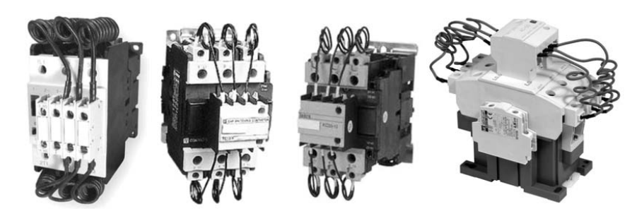
Capacitor duty contactors.
Contactor for capacitor switching
During switching of a capacitor, transient current of the order of 200 times the rated current can flow, stressing the capacitor and the switching contacts immensely. This can lead to damage or welding of contacts of the contactors.
Modern power factor correction systems use new generation contactors designed to switch the capacitors first through contact block of three early make auxiliary contacts in series with quick discharge damping resistor to limit inrush current to the value within contactor making capacity.
Normal rated capacitor current is carried by main contacts, which, after closing after about 5 milliseconds, effectively bypass the damping resistors. The leading contacts then open up, and no current flows through them.
Benefits of capacitor duty contactors:
- Saves cost of expensive replacements.
- Minimizes the effect of inrush currents.
- Saves energy; reduced watt loss during ‘ON’ conditions.
- Operator safety through IP 20 shrouds on power and control terminals.
- Higher safety in operations.
- Switching of capacitor bank in parallel without de-rating.
- Less maintenance and down time.
- Higher electrical life.
These capacitor duty contactors have become common in the past few years and a number of manufacturers have them in their regular product range.