
Harmonic Distortion Basics
Harmonics are sinusoidal waves that are integral multiples of the fundamental frequency 50/60 Hz waveform, depending upon different country norms (e.g. 1st harmonic or fundamental = 50 Hz; 3rd harmonic = 150 Hz, 5th harmonic = 250 Hz).
All complex waveforms can be resolved into a series of sinusoidal waves of various frequencies; therefore, any complex waveform is the sum of a number of odd or even harmonics of lesser or greater value.
Harmonics are continuous (steady-state) disturbances or distortions on the electrical network and are a completely different subject or problem from line spikes, surges, sags, impulses, etc., which are categorized as transient disturbances.
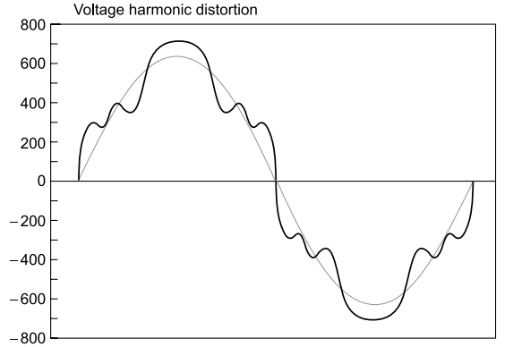
Any deviation from the sine-wave shape on a continuous basis is the indication of frequency other than the basic 50/60 Hz component. Distorted voltage and current waves cause voltage and current harmonics, respectively.
Current and voltage waveforms could be saw tooth, rectangular, symmetrical or asymmetrical, linear or nonlinear. Some waveforms are shown in Fig for clarification:
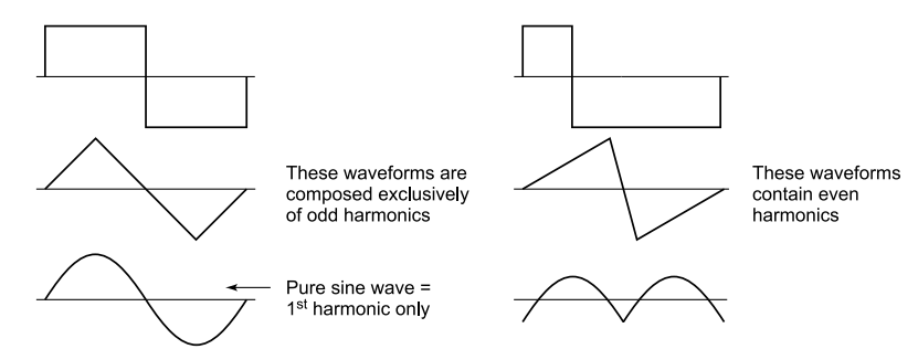
Some waveforms showing harmonics.
By definition, harmonic or nonlinear loads are those that produce a non-sinusoidal current when energized by a sinusoidal voltage source. Both current waveforms are produced by turning on some type of load device.
The distortion current could be produced by an electronic variable speed drive. The devices could be single-phase or three-phase. Power system harmonics are the mathematical integer multiples of the fundamental frequency within a power system.
These integer multiples represent the deviation of the electrical signal from a pure sinusoid to a distorted waveform.
Even though half of the possible harmonic frequencies are eliminated by the typically symmetrical distortion of nonlinear loads, the odd harmonics can still cause problems. Some of these problems are general to all power systems, single-phase or otherwise.
Transformer overheating due to eddy current losses, for example, can occur in any AC power system where there is significant harmonic content. However, there are some problems caused by harmonic currents that are specific to polyphase power systems.
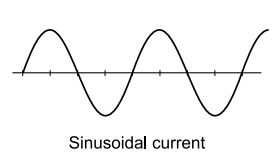
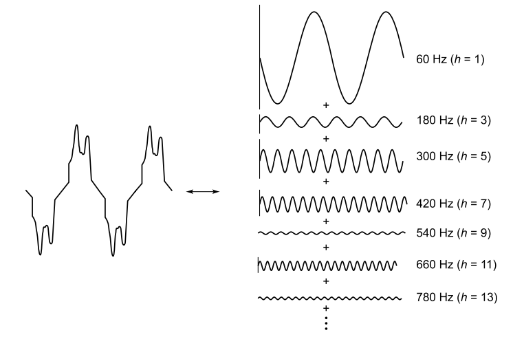
Non-sinusoidal currents.
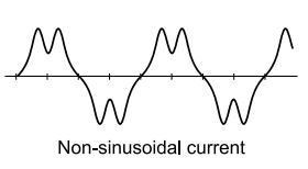
A distorted waveform can be looked upon as a combination of a number of harmonic waveforms, each one a sinusoidal one, but its frequency being multiples of the base frequency. Figure shows a distorted wave broken up into harmonic components.
Breakup of distorted waveform into harmonic contents.
One way to understand this is by imagining each harmonic frequency as a separate entity. As we add more current sources to the load, we would see further distortion of the line current waveform from the ideal sine-wave shape, and each of these harmonic currents would appear in the Fourier analysis breakup. Such a breakup can be understood with the help of Fig.
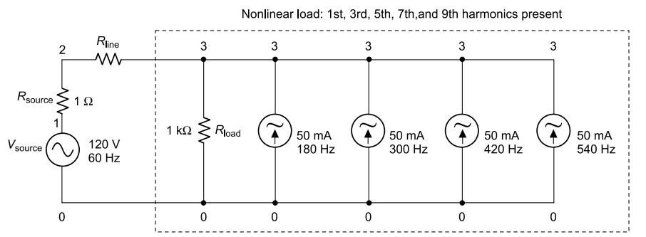
Total current as summing up of harmonic sources.
Due to their abundance and significance in three-phase power systems, the 3rd harmonic and its multiples have their own special name: triplen harmonics. All triplen (triple-n) harmonics get added to each other in the neutral conductor of a 4-wire Y-connected load.
In non-sinusoidal load systems, the triplen harmonic currents may be great enough to cause overheating of neutral conductors. This is a great nuisance, as safety concerns prohibit neutral conductors from having over-current protection, and thus there is no way for automatic interruption of these high currents.
Figure shows the addition effect of triplen harmonic currents created at the load in the neutral conductor, ω being angular velocity of the fundamental frequency, 3ω the 3rd harmonic, 5ω the 5th harmonic, and so on.
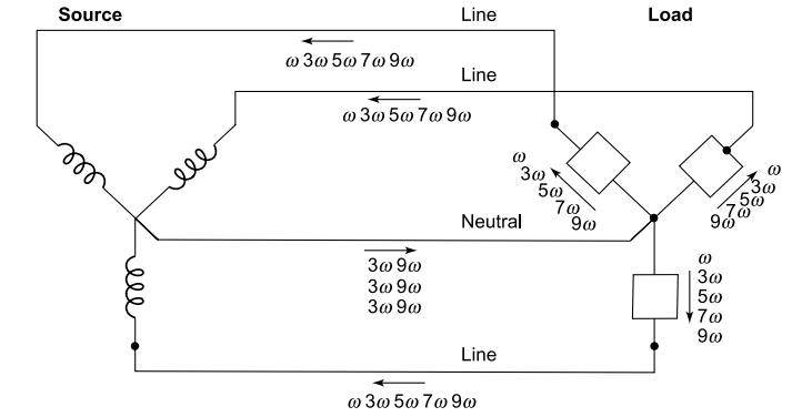
Triplen harmonics add in neutral conductor.
Origins of harmonic distortion
With AC power systems the source voltage waveform from an AC generator (alternator) is ideally supposed to be a single-frequency undistorted sine wave, without any harmonic content. It is a known fact that generator output voltage in industry or at home is invariably non-sinusoidal.
The nonlinear components draw current disproportionately to the source voltage, causing non-sinusoidal current waveforms. Distortion also occurs in transformers, whose primary winding magnetization current is usually non-sinusoidal due to the B/H saturation curve of the core, and in electric motors, when magnetic fields in the core operate near saturation levels.
Even incandescent lamps generate slightly non-sinusoidal currents, as the filament resistance changes throughout the cycle due to rapid fluctuations in temperature. Harmonic disturbances are further created by loads such as:
- Arc furnaces
- Thyristor controlled drives
- Oversaturated transformers
- Uninterruptible power supplies (UPS)
- Variable frequency drives
- DC variable speed drives
- Energy saving lamps
- Welding equipment
- Nonlinear loads
- Battery chargers
- Electronic equipment with SMPS
All these loads draw highly distorted currents from the distribution system. These currents result in voltage distortions everywhere, resulting in further problems.
Single-phase distorting loads like electronic ballasts and single-phase input UPS units are more troublesome since they draw triple-n harmonics: predominantly third harmonic.
Triple-n harmonics add in the neutral, overload the neutral conductors and form a possible fire hazard in systems with excessive distorting loads.
These devices have become quite common in our everyday life and in industries. One way to mitigate the distortion is to install reactors for such harmonics so as not to exceed capacitor current limits. Transient over-voltage also needs to be controlled using series reactors or with internal capacitor protection.
DG sets as harmonic source
An AC voltage source is ideal if (i) its source impedance approaches zero (ii) its frequency is constant, independent of load changes (iii) its voltage is constant and independent of extraneous load conditions, and (iv) its open circuit voltage is pure sinusoidal.
A Diesel Generator (DG) set is poor on all four counts. A utility supply point is much better on all the four counts. The frequency of utility supply may be considered practically constant, whereas DG set output voltage changes in response to every minor or major load change.
The source impedance/reactance of a DG set for harmonic frequencies and sudden transients is usually three to four times that of a similarly rated power distribution transformer.
For example a 500 kVA 11 kV/440 V distribution transformer may have 4.3% leakage impedance (500 kVA G set will have about 16% transient reactance) and for a DG set to have the same reactance as a 500 kVA transformer, it has to be 2 MVA DG set, which is impractical monetarily.
DG set voltage waveform.
Large synchronous generators at utility generating stations are optimized to generate almost pure sinusoidal voltage on no load. DG sets are not. Usually DG sets are designed to eliminate the fifth harmonic; but that leaves the third harmonic in the phase voltage unattended.
If the user does not connect single-phase voltage, the line voltages will not contain the third harmonic – but single-phase equipment is common and if such equipment is sensitive electronic equipment, the third harmonic content in the voltage of most DG sets is problematic.
Harmonics due to electronic sources
The ever-increasing demand of industry and commerce for stability, flexibility and accuracy of control in electrical equipment has led to the development of low-cost semiconductor control devices.
With the wide use of rectifier circuits (the picture below) for UPS systems, static converters and AC and DC motor control, these modern devices have replaced older generation mercury arc rectifiers and created new and challenging conditions for system designers today.
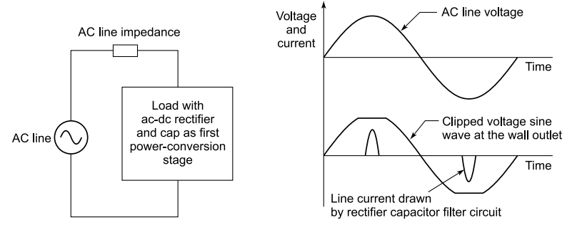
Harmonics from a rectifier.
The new solid state devices have brought significant improvements in control designs and efficiency, but the harmonic currents these devices produce can cause a disturbance on the supply network, and adversely affect the operation of other electrical equipment including power factor correction capacitors.
Most power supplies for DC devices like laptops exert a nonlinear load on the mains, their current draw often looks like this.
In amplifiers and some other electronic equipment, the THD depends on the load or the output.
The total harmonic distortion, measured with an input signal at 1 kHz at output power of 10 Was plotted against output power in Fig is less than 0.2%, and nearer to 0.15%.
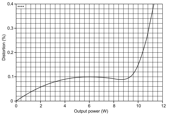
Total harmonic distortion plotted against output power for 10W amplifier.
Problems caused by harmonics
- The third harmonic and multiples of the 3rd harmonic in neutral grounding systems may necessitate de-rating of neutral conductors.
- Noise that leads to erroneous operation of control system components like tripping of circuit breakers and fuses.
- Overloading of transformers, capacitors, electric motors, fluorescent lighting ballasts and other electrical distribution equipment, causing overheating and failures.
- Nuisance tripping of circuit breaker or blown fuses.
- Harmonics means additional system losses.
- Measurement errors of energy counters.
- Damage to sensitive electronic equipment.
- Malfunction of computers and other electronic equipment.
- Electronic communications interference.
- Series and parallel resonance.
Harmonic content
Thyristors, SCR converters or rectifiers are usually referred to by the number of DC current pulses they produce in each cycle, the most common being 6 pulse and 12 pulse.
Many factors can influence the harmonic content but typical harmonic currents, shown as a percentage of the fundamental current, are shown in Table. Other harmonics, though always present to some degree, need not be considered, being very small.
Table Typical Harmonic Content in Thyristor Output
| Order of harmonic | Typical percentage of harmonic current | |
| 6 pulse | 12 pulse | |
| 1 | 100 | 100 |
| 5 | 50 | – |
| 7 | 14 | – |
| 11 | 9 | 8 |
| 13 | 8 | 8 |
| 17 | 6 | – |
| 19 | 5 | – |
| 23 | 4 | 4 |
| 25 | 4 | 4 |
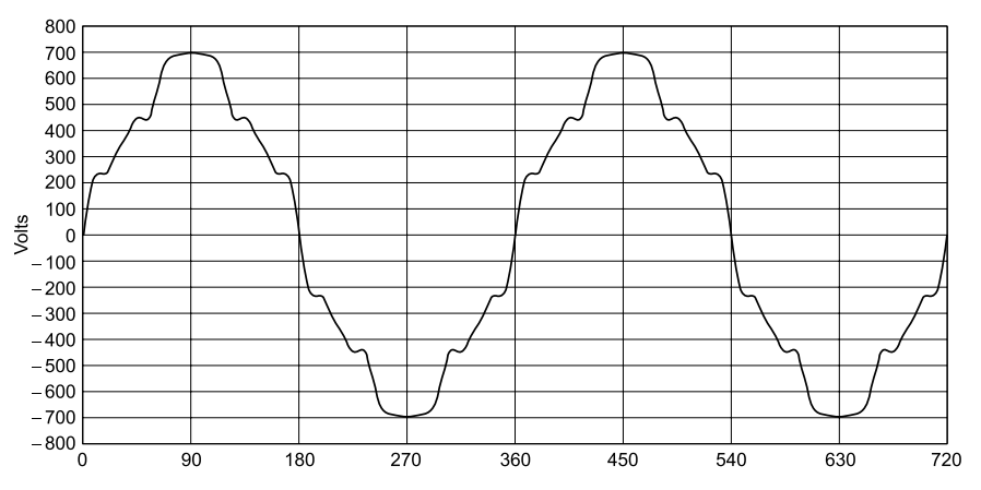
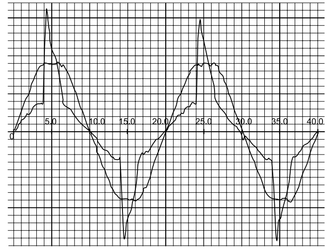
An idea of harmonic components may be obtained from a distorted waveform component breakdown given in Fig, showing waveform of harmonics up to 11th harmonics, and actually consisting of harmonics up to 19th harmonics.
This very badly distorted (18% THD) voltage waveform has 15% 5th harmonic, 6% 7th harmonic, 6% 11th harmonic and 4% 13th harmonic.
Total Harmonic Distortion (THD)
The series of harmonic components that represent a distorted waveform are often described by a single number, total harmonic distortion (THD). This is calculated as the sum of all the harmonic components (except the fundamental), divided by the magnitude of the fundamental.
It will be of interest to note that an odd harmonic added to the fundamental produces two different waveforms, depending upon the phase difference at zero crossing, as shown in Fig. The goal is to limit voltage harmonic to 3% and THD to 5%. As a guide, THD is the square root of the sum of measured harmonic components in percentages.
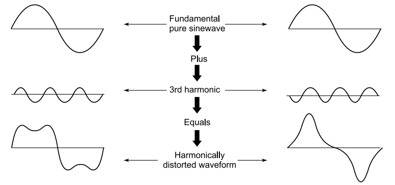
THD with 3rd harmonic dependent on phase difference.
Harmonics can be a particular concern for industrial water treatment facilities, since they typically utilize variable frequency drives (VFDs) for their operations. While conventional power distribution systems have to deal with significant amounts of non-sinusoidal current, IEEE guidelines and basic software tools may be used to curtail circuits and load configurations that lead to harmonic distortion problems.
Harmonics are considered as elements of power factor because of their relationship to the power-line frequency. As Fourier components, they cumulatively represent an out-of phase current at the fundamental frequency.
Harmonic overloading of capacitors
The impedance of a circuit dictates the current flow in a circuit. As the supply impedance is generally inductive, the network impedance increases with frequency while the impedance of a capacitor decreases.
This causes a greater proportion of the currents circulating at frequencies above the fundamental supply frequency to be absorbed by the capacitor, and all equipment associated with the capacitor.
In certain circumstances, particularly near resonance, harmonic currents can exceed the value of the fundamental (50 Hz) capacitor current. These harmonic problems can also cause an increased voltage across the dielectric of the capacitor which could exceed the maximum voltage rating of the capacitor, resulting in premature capacitor failure.
Harmonic Resonanc
The circuit selective resonant frequency is reached when the capacitor reactance and the supply reactance are equal. Whenever power factor correction capacitors are applied to a distribution network, which combines capacitance and inductance, there will always be a frequency at which the capacitors are in parallel resonance with the supply.
If this condition occurs on, or close to, one of the harmonics generated by solid-state control equipment, then large harmonic currents can circulate between the supply network and the capacitor equipment. These currents are limited only by the damping resistance in the circuit.
These will add to the harmonic voltage disturbance in the network, causing an increased voltage distortion. This results in a higher voltage across the capacitor and excessive current through all capacitor components.
Resonance can occur on any frequency, but in general, the resonance we are concerned with is on, or close to, the 5th, 7th, 11th and 13th harmonics for 6 pulse systems.
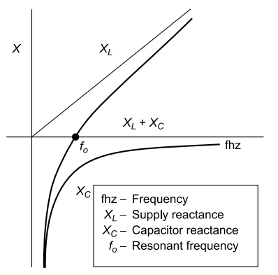
Harmonic resonance frequency f0[XL = Xc]
The IEEE 519 – 1991 Standard
The Institute of Electrical and Electronics Engineers (IEEE) has defined acceptable limits of current and voltage harmonic distortion for various types of systems. Voltage distortion in general systems should be limited to 5% THD, according to the standard. Special, critical applications should limit the THD to 3%.
IEEE 519-1991 (IEEE Recommended Practices and Requirements for Harmonic Control in Electrical Power Systems) defines current distortion limits for various ratios of source short circuit current (ISC) to load current (IL) – (The short circuit current for a transformer may be obtained by dividing the full load current [A] by the output impedance [%Z].)
The standard further limits total current harmonic distortion to 5% of the full load current of a transformer, unless the transformer is specifically designed for operation under loads with higher harmonic content.
Many users specify IEEE voltage and current harmonic distortion limits of 5% for their entire power system. (Or, for large systems, a complete branch served by a substation transformer.) They provide details of the proposed installation, including the following:
- Source transformer KVA and %Z (or source fault current),
- Distance from the source transformer to the PCC and the conductor type (busway or cable),
- Distance from the Point of Common Connection (PCC) to the VFD and the conductor type (busway or cable),
- Number and horse power (HP) of VFDs for connection to each PCC (usually the metering or incoming service point, or the point in a plant where the equipment is connected)
- Information about the harmonics generated by other loads connected to the same PCC.
- Voltage distortion limits established by IEEE-standard 519 are:
- 3% THD-v for hospitals and airports,
- 5% THD-v for general systems, and
- 10% THD-v for dedicated systems (where 100% of the load is nonlinear).
A simple one-line diagram of the VFD system can provide this information for analysis. Most VFD manufacturers have computer programs that can use this data to determine whether reactors, isolation transformers or phase shifting transformers are required for calculated compliance with IEEE 519-1991.
The golden rule is “You shall not draw so much distorted current that you upset the voltage waveform”.
- A utility must limit the VOLTAGE THD at PCC to under 5%
- A consumer must limit usually the CURRENT THD to below 5%
Harmonic mitigation techniques
[A] Harmonic analysis
The first step in solving harmonic problems is an analysis to determine the specific nature of the electrical distribution system, to establish the impedance of the supply network and the value of each harmonic current.
A detailed computer analysis can then decide the capacitor, reactor and filter bank equipment needs. Three options are available to solve the problems:
1、Use of correct amount of capacitance (KVAR) in the network to avoid resonance with the source – it may be difficult, especially in automatic systems, as the capacitance is always changing. This solution usually implies connecting smaller capacitance to the system than is optimally needed for power factor correction.
2、Install reactors in series with capacitors to lower the resonance below critical order
harmonics; i.e. 5th, 7th, 11th and 13th. This design tunes the resonant frequency of
the system well below the critical harmonic and is called an anti-resonance bank. The
capacitors then operate in a harmonic environment.
3、Filters are recommended if the harmonic distortion is above the limits recommended in IEEE 519, “Guide for Harmonic Control and Reactive Compensation of Static Power Converters”. (The recommended limits for voltage distortion in IEEE 519 are presently 5% for general applications.)
Tuned filters of proper size can reduce the harmonic distortion at critical frequencies and give the benefits of correcting the power factor and improving the network power quality.
Computer techniques for harmonic analysis
1、Simple radial networks can sometimes be analyzed utilizing simple calculations, though calculations become more cumbersome as the circuit complexity increases. Most common computer techniques are based on nodal admittance equations for the network.
2、Commercially available software tools facilitate harmonic analysis of complex systems and loads, and provide a graphical interface to build a variety of circuit types and multiple independent systems of different voltage levels. They also contain large amounts of data for different load and supply systems in memory, which make calculations easier.
[B] Harmonics attenuation
Harmonic current distortion is affected by the circuit impedance. Placing the same harmonic producing load at different nodes in a power system will result in different levels of distortion. This attenuation effect is used as one method of passive harmonic mitigation.
Introducing a series line reactor (or inductor) at the terminals of a 100 HP pulse width modulated (PWM) adjustable speed drive (ASD) can lead to a reduction of total harmonic distortion associated with the ASD from about 81% to 38%. The THD of voltage and current can be calculated using the relations

The ASD operation is not adversely affected, provided the line reactor chosen for the application does not exceed approximately 5% impedance relative to the drive base.
[C] Harmonics cancellation
Cancellation of harmonics can also occur because individual harmonic components of a distorted current are affected differently when passing through normal power system transformers. The magnitude of harmonic currents, like the 50 Hz component, increases or decreases consistently with the transformer turns ratio.
The phase angle of harmonic components, however, is influenced by the type of connection of the three-phase transformer. The 5th and 7th components, for example, experience a 30° phase angle shift through a power system transformer connected delta-wye, as compared with the same current components transmitted through a wye-wye or delta-delta connected transformer.
[D] Reduction of Harmonics
Harmonics can be reduced by tuned filter or passive filter. A tuned capacitor bank consists of a series circuit of capacitor(s) and specific filter circuit reactor, similar to a detuned unit. The difference is the resonance frequency.
Tuned filters are tuned very close to harmonic frequencies. The respective harmonic is absorbed by filters tuned to that particular frequency. Capacitors and reactors used for tuned filtering are specially made to withstand heavy harmonic current.
Passive LC filters are used on systems with electronic power factor controllers, which are a source of harmonics due to their thyristor circuits.
[E] Avoiding resonance
There are a number of ways to avoid resonance when installing capacitors. In larger systems it may be possible to install them in a part of the system that will not result in a parallel resonance with the supply.
Varying the KVAR output rating of the capacitor bank will alter the resonant frequency. With capacitor switching there will be a different resonant frequency for each step. Changing the number of switching steps may avoid resonance at each step of switching.
Transient problems are usually solved by installing suppression or isolation devices such as surge capacitors or isolation transformers. These devices will help solve the transient problems but will not affect the mitigation of low order harmonics or solve harmonic resonance problems.
A capacitor can be protected from overloading due to harmonics using detuned reactor. A detuned capacitor bank consists of a series circuit of capacitor(s) and a specific filter circuit reactor. The resonance frequency of a detuned bank is heavily detuned, mean it is not close to any existing harmonic.
The purpose of these capacitors is specifically to avoid tuning to any frequency where harmonics may be present. Hence these reactors are termed ‘detuned reactors’ and the bank as a whole is called a detuned bank. The basis for calculation of detuned capacitors is given in Appendix H.
[F] Overcoming resonance
If resonance cannot be avoided, an alternative solution is required. A reactor must be connected in series with each capacitor such that the capacitor/reactor combination is inductive at the critical frequencies but capacitive at the fundamental frequency.
To achieve this, the capacitor and series connected reactor must have a tuning frequency below the lowest critical order of harmonic, which is usually the 5th. This means the tuning frequency is in the range of 145 Hz to 220 Hz, although the actual frequency will depend upon the magnitude and order of the harmonic currents present.
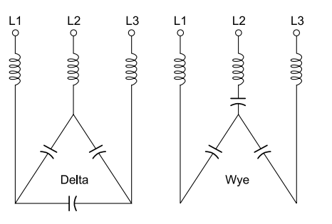
Filters for individual harmonics.
The addition of a reactor in the capacitor circuit increases the fundamental voltage across the capacitor. Therefore, care should be taken when adding reactors to existing capacitors. It is usual to increase the delta connected capacitor rated voltage to 525 V for 440 supply voltage when used with reactors.
[G] Reduction of harmonic distortion
Harmonic currents can be significantly reduced in an electrical system by using a harmonic filter. Basically, a filter consists of a capacitor connected in series with a reactor tuned to a specific harmonic frequency. In theory, the impedance of the filter is zero at the tuning frequency; therefore, the harmonic current is absorbed by the filter. This, together with the natural resistance of the circuit, means that only a small level of harmonic current will flow in the network.
Choice of filters
The effectiveness of any filter design depends on the reactive output of the filter, tuning accuracy and the impedance of the network at the point of connection. Harmonics below the filter tuning frequency will be amplified. The filter design is important to ensure that distortion is not amplified to unacceptable levels. Where there are several harmonics present, a filter may reduce some harmonics while increasing others.
A good harmonic filter reduces the harmonics to less than 5% and overcomes all the problems related to it. Experience is extremely important in the design of such filters to ensure the most efficient and cost effective solution, while ensuring no adverse interaction between the system and the filter. Consequently, it is often necessary to use a multiple filter design where each filter is tuned to a different frequency, as shown in Fig.
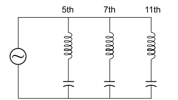
Filters for individual harmonics.
[H] Load alteration
Whenever load expansion is considered, the network may change and existing filter equipment has to be evaluated with the new load condition. Two or more filters tuned to the same frequency are not advised on the same distribution system.
Slight tuning differences may cause one filter to take a much larger share of the harmonic distortion. Or, it may cause amplification of the harmonic order which the equipment has been designed to reduce. When there is a need to vary the power factor correction component of a harmonic filter, careful consideration of all load parameters is necessary.
[I] A new approach – harmonic mitigating transformers (HMTs)
These are a relatively new design tool for transformers being used by some power quality professionals (including Reliant Energy, Houston, Texas) to rid commercial and industrial facilities of the power quality problems associated with harmonic currents.
HMTs have the ability to attenuate harmonic currents and thus alleviate power quality problems. In addition, by cancelling certain harmonic currents, HMTs can reduce the energy losses that harmonics would otherwise cause in conventional transformers.
These energy savings can offset the premium price for HMTs (which can be as much as 200%) and yield an attractive payback period. These are available in capacities from 15 to 500 kVA. All HMTs employ one or both of two approaches to combat harmonics, each of which addresses different types of harmonics.
The selection of the appropriate type of HMT depends on which harmonics are present in the electrical distribution system being treated.
(i) Single-phase loads
Single-phase electronic loads generate harmonics at all odd multiples, the most prominent being the triplens. In conventional transformers, triplen harmonics are transferred to the primary (delta) winding, where they are trapped and circulate continuously.
The distribution system upstream of this transformer is thus spared from having to supply triplen harmonics, but the harmonic currents cause excessive losses in the transformer.
HMTs attenuate triplen harmonics by using a “zig-zag” winding on the transformer secondary: this is a design that places half of the turns of each phase of the secondary around two of the legs of the transformer core (in the standard design, all turns for a given phase go around just one core leg).
This technique causes cancellation of the magnetic flux established by triplen harmonic currents, so little or none is transferred to the primary windings.
(ii) Three-phase loads
Harmonic problems in industrial facilities dominated by three-phase loads arise from currents flowing at the 5th, 7th, 11th, or even higher order harmonics. For these harmonics, HMTs use either dual secondary windings or pairs of transformers to achieve substantial attenuation of one or two of the most problematic frequencies.
In either design, the two secondaries are electrically phase-shifted relative to each other. The degree of relative phase shift is selected such that the targeted harmonic currents from one secondary are close to or exactly 180° out of phase with the targeted harmonic currents from the other secondary, and thus they cancel each other.
HMTs reduce electricity costs in two ways. They reduce losses directly by minimizing harmonic currents and their related losses in the transformer primary. If the HMT under consideration has a more efficient core and/or windings than the transformer it is being compared to, then direct losses at 50/60 Hz will be reduced as well, with additional cost savings.
HMTs may also contribute indirect savings if the transformers are to be located in air-conditioned space. Approximately 1 kilowatt-hour (kWh) of cooling system energy is required for every 3 kWh of heat removed. For HMTs installed in air-conditioned space, energy savings are therefore increased by about 33%.
Capacitor stress analysis
Electronic modules are available for the stress analysis of all power capacitors installed in the network, including those incorporated in filters. The analysis reports the harmonic currents and voltages of each capacitor as well as the total reactive power, RMS current, RMS voltage and peak voltage.
These quantities are compared to user-defined limits and any capacitor that violates any of those limits is reported and highlighted on a one-line diagram of the network.
This includes the following:
- Bar chart plots for voltage and current distortion versus harmonic order or frequency.
- Time waveform plots.
- Impedance magnitude and phase plots versus frequency, for resonance and de-tuning analysis.
- R-X plots.
- Sensitivity analysis plots.
- Possibility to plot multiple results on the same graph.
VFD Applications
Another software tool is available to facilitate a common harmonic evaluation task: application of VFDs to an existing low-voltage radial power system. While this tool is not accurate for complex systems, or for systems with power factor correction capacitors or harmonic filters, it is widely applicable for evaluating VFD applications.
Many designers use it for estimating the effect of variable speed drives (VSD) on a power system, as also a means of evaluating certain mitigating devices like line reactors and drive-isolation transformers, delta-wye transformer connections, and broadband filters.
Harmonics and smaller drives
The larger the VSD, the greater are the harmonics. However, a 250-hp drive is almost sure to attract much more attention from engineers than a 5-hp or smaller drive. Though this makes sense considering economics and effect on operations, there are times when a careful analysis of smaller horsepower drives becomes necessary.
On single-phase systems, drives will generate 3rd and, to a lesser degree, 5th harmonics. In commercial buildings, on four-wire systems (3-phase conductors and a neutral conductor), they contribute to the 3rd harmonic current adding up in a shared neutral.
This may necessitate installing neutral conductors twice the size of phase conductors. As small drives add their contribution to the total harmonic load, any line measurements (particularly current measurements) require a true RMS meter for accuracy.
In the presence of harmonics, average responding current meters can be inaccurate by as much as 40%.
On 3-phase systems, the 5th will be the predominant drive-generated harmonic. The 5th harmonic is a negative sequence harmonic: it creates reverse torque that will tend to make motors turn backward.
The 5th harmonic affects motors with across-the-line mechanical starters. The across-the-line motor, driven by the much larger fundamental current, will still turn forward, but the 5th will cause additional heating and, over time, can be extremely damaging to the stator insulation.
If a drive shares a bus with an across-the-line motor, such as in a motor control centre, it could damage the motor.
Note that this 5th harmonic will probably have virtually no effect on the upstream distribution system (i.e. cause minimal voltage distortion upstream), because its harmonic current is such a negligible portion of the total.
But at the local level, where source impedance is at its highest, a bank of low-horsepower drives can cause enough voltage distortion at the local point of common coupling (PCC) to affect the motor loads that share that PCC.
A 3-phase VSD draws nonlinear current, which injects harmonics into the power system. The 5th harmonic will be the predominant harmonic generated by the drive.
The first line of defence against harmonics should be in the drive itself. A reactor coil, sometimes called a link inductor, is integrated into the DC link of many drives and tends to reduce current distortion on the line side of the drive.
It also protects the drive from transient over-voltages (notably capacitor switching transients) that can travel to the DC link and cause DC over-voltage trips.
In some lower-cost drives, manufacturers cut costs by eliminating the reactor coil, making the drive, in effect, a ‘harmonics generator’. This is especially critical when you install the drive on a bus with an across-the-line motor. In this instance, you can correct the situation by installing input line reactors or isolation transformers.
Motor compatibility and smaller drives
VSDs can also create motor compatibility problems, especially when retrofitting drives to older motors. The high-speed switching of the insulated gate bipolar transistor (IGBT) in conjunction with long cable runs can cause over-voltage reflections (also known as standing-wave voltages or peak-to-peak or corona voltages) with peak voltages two to three times the DC link voltage.
Many drive manufacturers will specify cable not to exceed 30 m, but sometimes even this can be too long. These over-voltages tend to puncture insulation on the first few windings of the motor, causing premature failure of stator insulation.
This is a problem common to high- and low-horsepower drives with PWM outputs, but low-cost, low-horsepower motors are especially vulnerable. Their stator windings are often random-wound, a less costly manufacturing process, but one that could create a high potential between adjacent wires, making them that much more vulnerable to overvoltage reflections.
At one time, low-pass filters were commonly placed at the drive output to reduce the over-voltages. In recent years, however, manufacturers have designed inverter duty motors rated at 1500 V specifically to withstand over-voltage reflections. Many drive manufacturers now specify use of inverter duty motors with their drives.
If VSDs are generating harmonics, the first thing to do is take measurements at key points in the distribution system to determine the present level of harmonics. Measurements of harmonic distortion of waveforms as well as of individual harmonics may be taken with handheld power quality analyzers, or we may view over-voltage waveforms with handheld oscilloscopes.
The advantages of VSDs
Engineers have been able to cram more horsepower into smaller, more compact drives, to the point that low-horsepower drives now have more or less the same footprint as mechanical starters.
Hitherto, heat dissipation needs made it difficult to have smaller drives. A drive first converts the AC sine wave into DC and stores the power in DC link capacitor banks. The inverter then switches the DC to create a PWM signal of desired frequency. This process was a prime generator of heat.
In newer drives an IGBT has taken over the switching. Recent IGBT designs have greater current carrying capacity. IGBT switching speeds have become pretty fast, of the order of 100 to 200 nanoseconds. Except for a very small voltage drop across the semiconductor, these switches do not consume energy – the only wastage is by generating heat in the transition off to on and vice versa.
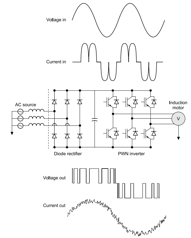
Current smoothing in PWM drive.
Higher switching speeds result in less heat loss and increased efficiency. The result is smaller heat sinks and fans and more compact drives. In addition to energy savings, drives offer many other benefits that contribute to the stability and robustness of the electrical distribution system:
- No inrush currents – they are typically limited to 110% of rated current. The inrush currents associated with starting motors can cause voltage dips or unwanted tripping of the motor. Soft start drives generally ramp a motor and load up to speed in about 20 to 30 s.
- High power factor, eliminating the need for power factor correction capacitors.
- Switching transients (spikes) are isolated when a motor is turned off (ramp down a motor over 20 to 30 s). At the final turn-off, the motor is at low-speed and low-current, the small spike is easily absorbed within the DC link section of the drive itself.
- Programmable motor control, protection, and even communication functions that are far beyond mechanical starter capacity. The drives may be programmed to reverse motor rotation, eliminating the need for an additional contactor.
- It is possible to replace single-phase motors with more rugged three-phase motors. This is because the VSD can accept a single-phase line-side voltage and output a three-phase signal on the load (motor) side. In other words, drives ‘transform’ single-phase to three-phase voltage.