
Power factor in supply systems
Most system loads in electric utilities, right from generation equipment, up to the final consumer systems, are inductive in nature. They load the system with a highly lagging current component. The result is a low power factor, with large overall current forced on the equipment, cable, transformers switch-gear etc.
This inductive component of current constitutes a lagging load, (called apparent or reactive load) and is represented as inductive KVAR. This component increases the supply line current considerably, causing under-utilization of available generation and distribution capacity at all levels.
Modern electric power utilities face many challenges due to ever increasing complexity in operation and structure, one problem receiving wide attention being voltage instability. Lack of new generation and transmission facilities, over-exploitation of existing facilities, coupled with increasing load demands aggravate these problems in modern power systems.
The main cause of voltage instability is the inability of the power system to meet the demand for reactive power. Voltage instability is the cause of system voltage collapse, when the system voltage decays to a level from which it is unable to recover.
Voltage collapse may lead to partial or full power interruption in the system. It becomes imperative to provide adequate reactive power support at the appropriate location to solve voltage instability problems.
Static voltage stability
Static voltage instability is mainly associated with reactive power imbalance. The loading capacity of a bus in a system depends on the reactive power support that it can receive from the system. When the system approaches the maximum loading point (or voltage collapse point), both real and reactive load components increase rapidly.
Hence the reactive power supports have to be locally adequate. The only way to save the system is to reduce the reactive power load (or add additional reactive power) prior to reaching the point of voltage collapse.
Capacitors are connected across the system at several places to compensate the lagging power factor by offering leading or capacitive KVAR in sufficient magnitude, to reduce line currents effectively and to achieve optimum load conditions so as to make maximum use of the equipment and the system.
The lower the power factor, the higher are the currents for the same active load (MW or kW). For better utilization of the system, it must be maintained at a lagging power factor of 0.95 and above.
Most utilities nowadays impose penalties for low power factors, and also offer incentives for higher power factor above 0.98. It makes sense to install capacitors on all systems to reduce line currents, lowering line losses, and also lowering switchgear requirements in many cases on this account.
Voltage fluctuations arising on systems are also taken care of with capacitors installed in position. System and generation capacities are released for addition of extra load.
In electric power distribution, capacitors are used for power factor correction. Such capacitors often come as three capacitors connected as a three-phase load, although single/two-phase power factor capacitors are not uncommon.
The capacitors are normally connected in delta, while it is general practice to have star connected capacitors for high voltage systems. Usually, the values of these capacitors are given not in microfarads, but in a more useful form as a reactive power output in kilo–volt–ampere reactive (KVAR).
They serve to counteract inductive loading from devices like electric motors and transmission lines to make the load appear mostly resistive to the supply side. Individual motor or lamp loads may have capacitors connected with them for power factor correction, and larger sets of capacitors (usually with automatic switching devices) are installed at a load centre within a building or in a large utility substation.
Benefits of power factor correction
- Power factor correction reduces the reactive power in a system and overall power factor of system is improved.
- Effective installation use: An improved power factor means an electrical installation works more economically (higher effective power for the same apparent power), and costs come down.
- Improved voltage quality: Capacitors generally improve the voltage regulation by decreasing voltage drop and absorbing some impulses.
- Fewer voltage drops, since lagging currents and hence overall current in the system are reduced. Capacitors cause a rise in voltage at the load centre due to this effect.
- Optimum cable dimensioning: Cable cross-section can be reduced with improvement of power factor (less current). In existing installations for instance, extra or higher power can be transmitted.
- Smaller transmission losses: The transmission and switching devices carry less current, corresponding to only the effective power, thus reducing the ohmic losses in the leads.
- Lower power losses up to capacitor locations, improving system efficiency.
While shunt capacitors offer several advantages at all voltage levels, they should be put in and out of circuit at appropriate times to get the most from the system. When load levels are high, a shunt capacitor system is beneficial.
When the load is off, however, the capacitor must be disconnected, as it can do more harm otherwise. An excess of capacitance in service can lead to higher voltages, excessively leading power factors and resonance problems.
Power factor correction
[A] Individual power factor correction of motors
Capacitors connected directly across motor terminals should just compensate for the no-load magnetizing currents of motors. If a loaded motor power factor is sought to be compensated, a capacitor of higher rating beyond a limit may pose a danger to the motor.
When the motor is slowing down, it gets over or self-excited. Over-voltage occurs when a motor and its capacitors are disconnected from line and the motor continues to rotate for some time. The motor acts as a generator, with the capacitor supplying the magnetizing currents.
Voltages across its terminals can go to over 140% to 160% with improper capacitors, causing damage to both the motor and the capacitor. Capacitors across motor terminals should be generally as per guidelines mentioned in the tables given in Appendix D.
Reactive power is required by an asynchronous motor for the magnetic field. The amount of reactive power consumption of a motor depends on various parameters such as power rating, loading, rated speed, and design.
The capacitor output should not exceed 90% of the apparent power of an asynchronous motor under no-load conditions. This is important to avoid dangerous self-excitation of the motor. A measurement of motor current under no-load conditions can be easily performed or may be obtained from the manufacturer.
Appendices D1 through D3 give the power factor of partially loaded motors, guidelines and standards for capacitor selection for power factor correction of motors.
[B] Individual power factor correction of welding machines
Resistance-welding machines are usually characterized by a large intermittent kilo–volt–ampere demand at low power factor, from 0.3 to 0.45, which is sometimes difficult to handle on the available power circuits due to regulation problems.
Welding loads present quite a challenge to the designers of power factor control systems because of the rapidly fluctuating current taken during the welding process. Connection of capacitors for power factor improvement is also not an easy task.
The output of capacitors for single and two-phase welding transformers and resistance welding machines needs to be up to 50% of the nominal transformer capacity. For welding rectifiers, a capacitor output of about 10% of the nominal capacity of the transformer/rectifier is sufficient.
Three-phase welding machines can be provided capacitors with around 33% of their KVA rating. Appendix E-2 gives recommended capacitor ratings for welding transformers.
It is standard practice to switch the capacitors on and off with the welding transformer to avoid loading the supply with capacitive current when not necessary. A specially designed current sensing relay and a fast discharging arrangement for the capacitor is deployed to adjust to the welding process at a fast rate.
The capacitor used for power factor is specially provided with an arrangement for quick discharge, so that it can be switched on again in a short time. This allows the controller to follow the welding cycle properly. Fuzzy logic current sensing relays are currently in vogue for accurate welding controls. Single-phase, two-phase as well as three-phase welders can be controlled in this way.
The load current is measured by the relay, and a contactor is switched on or off depending upon the fuzzy logic programmed into the controller. The contactor is used to switch the capacitor for improving the power factor. A fixed capacitor is used to compensate the inductance of a transformer.
[C] Individual power factor correction of power transformers
The voltage regulation of a transformer is the percentage change in the output voltage from no-load to full-load. As power factor is a determining factor in the secondary voltage, it influences voltage regulation.
This means the voltage regulation of a transformer is a dynamic, load-dependent number. The number of primary windings would not change; the number of secondary windings would not change, but the voltage regulation varies with the power factor.
Ideally, there should be no change in the transformer’s output voltage from no-load to full-load. In such a case the voltage regulation is said to be 0%. To get the best performance out of a transformer, voltage regulation should be the lowest possible.
This may be calculated from load conditions and the result saved as a troubleshooting and predictive maintenance benchmark. If the percentage change is too high, a check is needed for power factor correction for the loads on that transformer.
The direct connection of the capacitor to a power transformer, which is jointly switched in and out, is feasible and permissible both at the high voltage side and the low voltage side. In cases where harmonics exist in the line, the line should be checked to determine whether the capacitors and the power transformer create a resonance.
Care should be taken not to over-compensate the power transformer during low load operation in order to avoid an unacceptable rise in voltage.
For power factor correction of transformers only the no-load reactive power has to be covered. The required capacitor output for three-phase transformers depends on the short-circuit voltage and is between 3% and 12% of the rated transformer output.
In case harmonics are present on the high voltage side, the capacitor can form a series resonance circuit with the inductance of the transformer. Therefore the capacitor output has to be selected very carefully in collaboration with power utilities and the transformer manufacturer.
[D] Group power factor correction
With individual PFC, the capacitor is individually assigned or switched to a load. With group PFC, the power factor of a load group is determined with varying power configuration. Multiple capacitors are automatically switched in or out by a VAR controller.
The task of both application types is to improve the power factor and thus achieve a reduction of the reactive power. With group power factor correction, the physical arrangement of the contactors and capacitors is mostly in the proximity of the low-voltage transformer, e.g. in the low-voltage sub-distributor.
At this point, it is important to observe that the operating voltage and the short-circuit rating are higher during a fault.
The power factor correction capacitor is connected to the secondary distribution system which feeds a number of individual motors, operating either continuously or at intervals. The motors and the capacitors are each switched in and out separately and are monitored by separate protective devices. The capacitors can be switched in or out individually or in groups.
A single bank of power capacitor equipment can be used for a large group of small power consumer centres, e.g. motors. The reactive power consumption of such a group is widely variable, and a bank should be divided into several stages. The discussion here will exclude rotating machinery like synchronous compensation motors.
[E] Advantages of static shunt capacitors in group correction
- Low dielectric loss.
- Simple transport and construction. Large banks are built from small units.
- Any bank can be enlarged by simple addition of new units.
- The bank can be located near the consumer.
- Supervision and maintenance is simple. A damaged unit can be replaced easily.
Percentage apparent power (KVAR) reduction (or network unloading) related to power factor improvements are as per Table below.
Table Apparent power reduction with power factor improvement
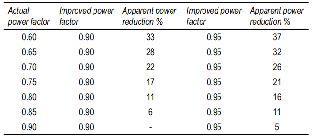
Network transmission losses in the form of heating are remarkable. Losses depend on the square of line current. These also get reduced with power factor improvement due to reduction in overall current.
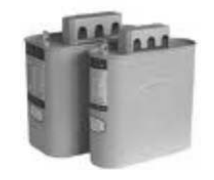
Shunt capacitors
These capacitors are connected in parallel to the load, and directly across the supply mains. Hence the name, ‘shunt capacitors’. These are by far the most commonly used for reactive compensation. Capacitors are available from 1 KVAR to 100 KVAR units, rated at 415/440 V for normal supply mains. Units for medium and high voltages are used on higher voltages.
These are most often meant for indoor use;although pole-mounted KVAR capacitors are also available. High voltage capacitors for outdoor installations are rated up to 11 kV. Most capacitors for 440 V supply mains are now being made with MPP film.
For highly fluctuating loads like sugar mills, rolling mills etc., film/foil capacitors or mixed dielectric capacitors are preferred on account of their surge current capacity and capacitance stability. MPP capacitors are normally used in most applications on account of their lower costs and self-healing ability.
Inductor coils are usually provided in series with capacitor elements, of a few micro henries to limit surge currents within manageable limits. Often means are provided like louvres to allow air-cooling.
The series reactor coils and discharge resistors are sources of heat generation, and the heat has to be dissipated. Smaller capacitors may have cable/wires coming out for connections, while most units are provided with bolt and nut arrangements for connections.
Brackets may be provided for wall mounting or panel mounting, and cable cover is provided over the terminals. Many capacitors are provided with internal or external fuses for protection. These are particularly necessary for higher voltages.
Units of shunt capacitors are connected in parallel to form banks of higher KVAR ratings. In these cases, a bus is provided per phase for making parallel connections, and often series reactors are connected between capacitor terminals and bus bar.
In case of capacitors connected in supply systems or automatic power factor correction panels (APFC panels), it is customary to add a series reactor, about 6% of capacitor reactance, to limit the surge and harmonic currents and protect the capacitor.
However, the reactor voltage being in opposite phase by nature, actual voltage across capacitor terminals becomes higher than supply voltage. Capacitor KVAR output goes up, and it is necessary to keep this increased voltage within capacitor ratings. Actual capacitor KVAR so connected will be higher than the system requirement by a factor equal to the series inductor KVAR.
It is possible to have single or two-phase capacitors rated 250 V or 440 V, to be connected across welding transformers or lighting load. For calculations, 1 KVAR at 440 V gives a capacitance value of 16.5 μF, while at 415 V, it comes to 18.5 μF. At 240 V (single phase), the capacitance value comes to about 56 μF per KVAR.
Considering the tolerance on capacitance values, which is −5% to +10%, the average target value is 3% above this level. This throws up a value of 5.65 μF per phase per KVAR of 440 V capacitor, and 6.3 μF per phase per KVAR for 415 V capacitors for three-phase units.
Values for any given KVAR rating can be calculated from this relation. When measuring capacitance across two terminals of a finished three-phase delta connected capacitor, the measured value on the meter shows one capacitor across terminals, plus two other capacitors in series coming in parallel (corresponding to other two phases).
Hence the measured capacitance is 1.5 times the value per KVAR, viz. about 8.22 μF between any two terminals per phase for a 440 V rated delta connected capacitor.
[A] Important considerations in use of shunt capacitors
Shunt capacitors are subjected to some of the most rigorous working conditions anywhere in industry. They are always subjected to full KVAR capacity, limited only by the applied voltage. Unlike motors or transformers, their load cannot be reduced or increased, and hence they are always fully loaded so long as they are connected to system voltage.
They have a tendency to offer feedback effect in the system in a way that the line voltages tend to rise on light loads. Predominantly capacitive loads are also harmful to the system and the system KVAR has to be maintained at a lagging power factor of 0.9 and higher.
For this purpose, KVAR capacitors have to be disconnected from the supply often depending upon load conditions. A capacitor, at the time of switching on, offers a temporary short-circuit like condition to the supply terminals, causing a heavy current inrush.
Further, sudden voltage fluctuation and transient conditions also result in heavy current surges in the capacitor. In metallized shunt capacitors, these current surges cause large current densities to occur at the metallized ends and also on the metallized electrode surface of capacitor elements.
When a capacitor is switched on and connected to supply, while other capacitors are already connected, this new capacitor offers a momentary short-circuit condition for all these capacitors (and the supply), and they get momentarily discharged through the new unit.
In metallized shunt capacitors, these current surges cause large current densities to occur at the metallized ends and also on metallized electrode surface of capacitor elements. A metallized capacitor has a tendency to self-heal under condition of transients, and hence the capacitance value and correspondingly KVAR output goes down with time.
This factor becomes predominant for fluctuating loads like sugar factories, rolling mills, drawing units, cable industry etc.
On account of these factors, non-metallized KVAR capacitors have come to stay as they are extremely stable and reliable for power factor correction, whenever frequent switching of capacitors like those in capacitor banks is involved.
A capacitor bank consists of a number of capacitors connected in parallel to each other. These capacitor banks may be made partially ON and OFF depending upon load conditions, in such a way as to maintain required power factor. The capacitors may be connected in regular three-phase systems, or even on single phase or two-phase loads.
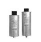
KVAR capacitor units and capacitor bank
[B] Capacitors used for utility and load power factor correction
These can be of the following types:
- MPP dry capacitor for power systems (shunt/KVAR capacitors)
- MPP oil impregnated capacitor for power systems.
In these self-healing capacitors, with every self-healing event, the capacitance value goes down in an infinitesimally small measure. Hence, MPP capacitor has a tendency to lose capacitance value over the years. The manufacturing processes have to be meticulously planned and carried to keep the good capacitance stability in service.
- Mixed dielectric shunt capacitor
These use a paper plus PP dielectric combination impregnated with oil, along with aluminium electrodes.
- PP/foil (All PP) shunt capacitors:
Only PP film and aluminium foil construction impregnated with oil are used in these capacitors.
The list is not exhaustive and covers some of the prime areas of use.
The foil-type non-self-healing capacitors are very stable and do not undergo capacitance change in their service life. PP/foil capacitors are the most expensive but best in performance, while dry MPP capacitors are the most cost effective. The cost of different types of capacitors increases from (i) to (vi) above.
Series reactors
Reactors are used in series with capacitor banks for two reasons:
- To dampen the effect of transients during capacitor switching.
- Control the natural frequency of capacitor banks and system impedance to avoid resonance and to sink harmonics.
In many applications, current limiting reactors are all that is needed for safe operation of capacitor banks and the network.
Modern systems of speed control and voltage control frequently use thyristor drives, which use chopping circuits, causing highly distorted wave shapes. The system uses complicated electronic systems to correct the wave shape to near sine wave, while keeping the power factor near unity.
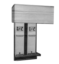
Series capacitors
Series capacitors are connected between transmission point and load, and become a part of series impedance of the transmission line, as in Fig Any change in load automatically affects the capacitive voltage drop and partly compensates for the change.
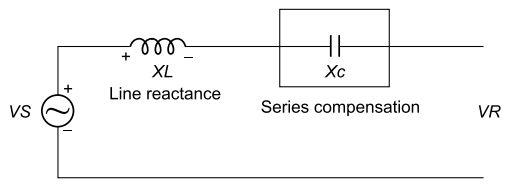
Series capacitor in a line
By adding series capacitance, it can be seen that the receiving line end voltage will be closer to the sending line end voltage. This decrease in voltage drop across the line allows more power to be transferred over the line for any given sending line end voltage. Practical installation of a series reactor can be seen from Fig.
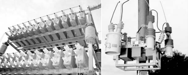
Series capacitor banks
The benefits of series capacitors are that they:
- Increase power transmission capability
- Improve power system transient and steady state stability
- Reduce system losses
- Improve voltage profile of the lines
- Optimize power flow between parallel lines
Construction of KVAR capacitors
Basically, shunt capacitors are three sets of capacitors connected internally or externally in a star or delta three-phase system, with common terminations or bushings brought out for cable connections.
The three sets of capacitors may be winding elements in a common container, or independent capacitors may be mounted in a common box and interconnected. Sometimes the three separate sets of terminals are brought out, making it a six-terminal capacitor. The interconnections are made by the user on site.
The size and rating of capacitors may be decided by the KVAR required and voltage rating. The capacitors may be of any of the representative types below:
- Paper/foil/oil – This is now almost obsolete.
- PP/Paper/foil/oil – Mixed dielectric non-metallized.
- Hazy PP film/foil/oil – All PP capacitor.
- MPP (dry) – MPP in metal or plastic can, resin encapsulated.
- MPP (impregnated) – MPP impregnated in oil.
- MKV (double metallized paper/PP or paper/oil) – Electrode formed by metallizing on both sides of paper without margin, and oil impregnated.
- MKP (double metallized PP/PP/oil) – Electrode formed on PP film both sides metallized,
- used with plain/hazy film dielectric, oil impregnated.
- Hazy PP film/foil + both sides metallized film, oil impregnated.
- Segmented film, resin encapsulated.
Essential parts of shunt capacitors are:
- Capacitor elements/capacitors and their interconnections.
- Internal insulations.
- Impregnation fluid (in oil-filled capacitors).
- Bushings/terminals/lead wires.
- Cover, where provision for cable connection is made.
- Mounting provisions.
- Discharge devices between terminals. Each capacitor unit is provided with means for discharging to 50 V or less within one minute of disconnection from supply. The following may be used as discharge devices:
- Discharge resistors
- Discharge coils
- Discharge transformers
- Windings of motors or transformers (where capacitors are connected directly against motor or transformer terminals)
- Series inductors – these may be inside or outside capacitor units. Their purpose is surge current dampening.
- Earthing provisions with marking.
Specifications and Terminology: The following standard systems are used for capacitor specifications and calculations.
Rated output of a capacitor: Reactive power derived from the rated values of capacitance, voltage and frequency. This may be calculated from three single-phase capacitance measurements, ammeter voltmeter method or KVAR meter.
Tolerance: Capacitance and output shall have a tolerance of (a) −5 to +10% for units up to 100KVAR, (b) – 0 to + 10% for units and banks above 100 KVAR, with the condition that in three-phase units, the ratio of maximum to minimum values measured between any two terminals shall not exceed 1.05.
The basic formula for individual capacitor per phase is
VAR=V×I=V×ωCV=2πfCV2=314CV2 for 50 Hz,where C is in farads. In a balanced system, actual VAR is 3 times this figure, and KVAR = VAR/1000.
For a three-phase delta connected system, VA= √3 × VI,where I is the line current in each phase of the balanced system. The line current is approximately 1.31 amp per phase per KVAR value of capacitor in a balanced system for 440 V supply.
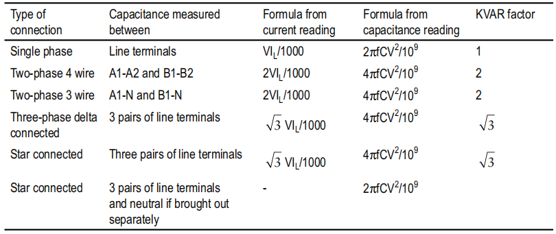
Table below gives the method for calculation for different connections and configurations of capacitors, both by current measurement method and capacitance reading method.
Table Reactive Outputs for Different Connections
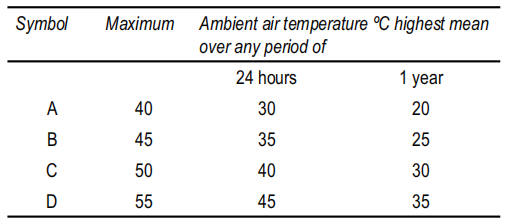
Climatic category for KVAR capacitors: Climatic category of a power capacitor is denoted by a symbol representing the climatic temperature range it can withstand in service.
Since the temperature of a place keeps varying over the year, and also with the time of day, these are taken into account when deciding the maximum category temperature. These are specified in Indian standards by symbols as in Table below.
Table Climatic Category of Power Capacitors Defined in Indian Standards
Permissible overloads on power capacitors: The capacitors in service are subjected to frequent fluctuations of voltage and transients. The load is always changing, and as a result, voltage and current are ever fluctuating, and harmonics are also present.
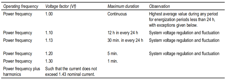
These factors have to be within the following limits: Capacitors have to bear variations as per Table below as specified in the Indian standards during their operation in supply systems.
Table Permissible Overloads for Power Capacitors
Economic considerations power factor correction
Electrical power administrators of all countries with relatively developed industries promote installations of power factor improvement systems, by penal rate charging for low power factor, and many times giving incentives for power factor closer to unity.Sometimes even the reactive power is charged.
Savings due to reduced power system losses and financial results based on higher system efficiency, stability as well as reduced need for new generation capacity are of paramount importance for the national economy.
A power price policy, i.e. selling price level for active and reactive power, or by way of penalty for low power factor, is of crucial importance for a successful economic approach. In most countries, the investments on a low voltage power capacitor bank are recovered in 2–3 yrs. After this period, the banks earn net profit.