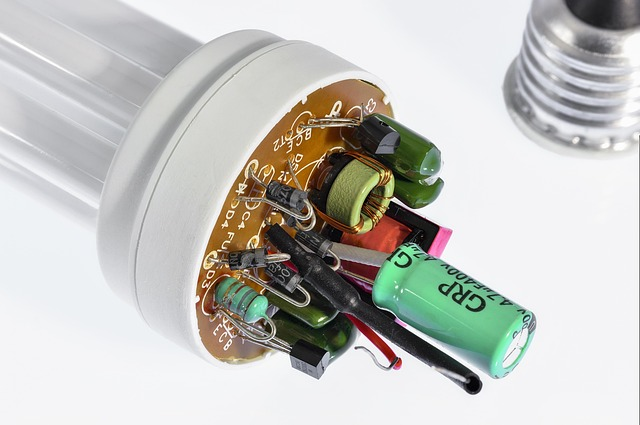
The manufacturing process of aluminum electrolytic capacitors is mainly for the slitting, nailing, impregnation, assembly, casing, aging, testing of positive foil, negative foil, electrolytic capacitor paper, etc.
Slitting
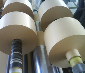
The 40~50cm wide aluminum foil coil is corroded and cathodicly oxidized, and then divided into the required width according to the length of the capacitor.
The quality requirements of the slitting process are that the slitted aluminum foil, electrolytic capacitor paper winding electrolytic capacitor has the best possible performance and quality.
First of all, aluminum foil and electrolytic capacitor paper need to be as flat as possible after slitting to roll out the core with consistent tightness everywhere.
Then, the burr length of the aluminum foil incision is as short as possible to reduce the aging defects in the aging process as much as possible, and to minimize the power-on convex bottom or even the bursting of the electrolytic capacitor.
For the manufacture of electrolytic capacitors, the slitting of aluminum foil, especially the cathode foil, has a great impact on the quality of electrolytic capacitors, so this is an important process.
Slitting can also be done by an aluminum foil slitting manufacturer, who only needs to purchase slitted positive foil, negative foil and electrolytic capacitor paper.
Slitting machine
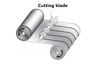
Slitting process
The slitting machine slits aluminum foil or capacitor paper into winding aluminum foil and capacitor paper of various types of electrolytic capacitor cores, which requires width.
Aluminum foil is slitted with a blade to slit, and the slitted foil or capacitor paper is wound into a new roll that can be installed on the winder.
The quality of aluminum foil slitting of electrolytic capacitors can be judged from the burr of the slitting, the consistency of the slitting width, the distortion and flatness after slitting.
Burr is the determining factor of the quality of electrolytic capacitors, if the aluminum foil after slitting, especially the positive foil, has burrs, it will lead to poor aging of the electrolytic capacitor, and even implosion in the client due to poor aging.
Poor twisting and flatness will lead to slackening of the core after winding, and even an increase in the rate of defective products or an increase in the early failure rate of the client.
Nailing
The electrolytic capacitor core can be nailed with slitted positive foil, negative foil, and electrolytic capacitor paper.
Nail roll is two actions. Nailing is to “nail” a guide pin (lead pin electrolytic capacitor) or a guide strip (pin or bolt electrolytic capacitor) to the positive and negative electrode foils to realize the lead electrode of the electrolytic capacitor.
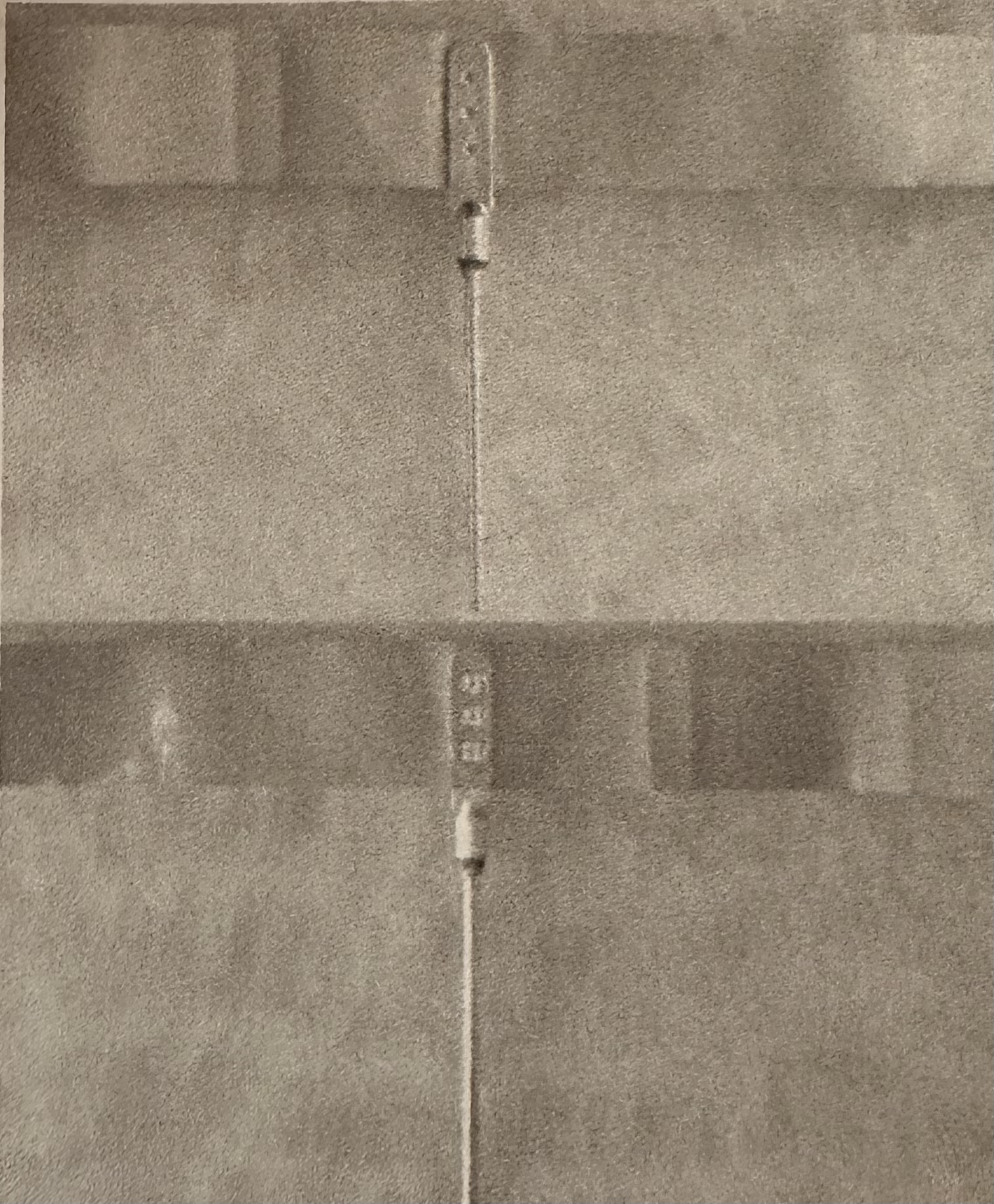
The rivet flower after flattening the normal rivet joint
The process of nailing is divided into riveting and squashing (or flattening).
The riveting process is to attach the guide pin or guide strip to the pre-designed position of the aluminum foil during the nailing process, and then pierce the guide pin or guide strip through the riveting, so that the guide pin or guide strip is riveted on the aluminum foil to form a mechanical bond and good electrical conductivity.
The flattening process is to flatten the burrs generated by the riveting process to avoid the formation of new burrs, and the aluminum foil cannot be cracked. In particular, high-voltage aluminum electrolytic capacitors with small capacitance have relatively narrow aluminum foil and relatively low mechanical strength, and it is easy to crack the aluminum foil if it is not handled well.
In fact, the staple roll is realized on the same staple roll machine. On the nailing machine, the aluminum foil goes to the predetermined position, and the positive guide pin and the positive foil are riveted and flattened, and the negative guide pin and the negative foil are riveted and flattened, and the positive foil and negative foil respectively “walk” to the winding position with the guide pin.
Wrap the positive foil, negative foil, and electrolytic capacitor paper alternately, and cut off the aluminum foil after obtaining the predetermined number of winding circles or lengths, and wrap the aluminum foil on the electrolytic capacitor paper and fix it with tape.
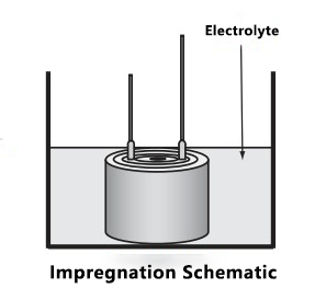
Impregnation
The actual negative electrode of an electrolytic capacitor is the electrolyte, and the electrolyte in an electrolytic capacitor can be carried by impregnation of capacitor paper.
In order to ensure that the capacitor paper is saturated with the impregnated electrolyte, it is necessary to remove the gas from the core package, especially the gas in the capacitor paper, so it is necessary to impregnate the electrolyte in a vacuumed environment.
Seal
The electrolyte is easily volatile at high temperatures, resulting in a reduction in the effective area of the negative electrode, so the electrolytic capacitor needs to be sealed.
In the 60s or earlier years of the 20th century, in order to reduce the cost and reduce the amount of aluminum (the output of aluminum was not high at that time and the aluminum in China at that time was mainly used to manufacture aircraft), commercial electrolytic capacitors (then called civilian products) basically used wax paper tubes and both ends were potted with resin, due to poor sealing, most of them failed after several years of use, and the working temperature was only 55 °C.
Sometimes it only takes one or two years to completely fail, such as the steamboat sound of the tube radio is the self-excitation phenomenon caused by the harmful coupling caused by the high AC impedance of the power supply, which is the manifestation of insufficient capacitance left after the electrolyte volatilization in the electrolytic capacitor, and the serious AC sound tells the filter electrolytic capacitor to completely fail.
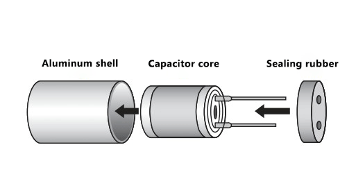
Today’s electrolytic capacitor cartridges are sealed inside a container. Most of the containers are made of aluminum, and the container port is pressed with a well-sealed rubber stopper or rubber pad and resin plate to effectively prevent the volatilization of the electrolyte.
In order to prevent the explosion of the electrolytic capacitor due to gas pressure in the event of a fault, the electrolytic capacitor with a diameter of more than 8mm is equipped with a pressure relief device, which is usually engraved with K, >, Y and x-shaped indentations on the end face of the aluminum shell, so that the internal air pressure of the electrolytic capacitor expands and the rubber plug is broken and relieved.
The steps to seal are as follows:
1) The lead pin electrolytic capacitor needs to pass the guide pin on the impregnated core through the hole reserved by the rubber plug and insert the rubber plug on the core. The force of the rubber plug is too large, so that the guide pin vigorously rubs the electrolytic capacitor paper, resulting in the electrolytic capacitor paper being damaged at the friction part and the voltage resistance is insufficient.
For plug-in or bolted electrolytic capacitors, the lead strip of the impregnated electrolytic capacitor core is tightly riveted to the rivets of the cover exit electrode.
In this process, the positive and negative poles of the electrolytic capacitor need to be clearly distinguished.
Pin type electrolytic capacitors use long and short lead pins to distinguish the positive and negative poles of electrolytic capacitors.Pin electrolytic capacitors and bolt electrolytic capacitors use an asymmetrical method to confirm the positive and negative poles of the lead strip.
Then press out the pitting on the electrode rivet on the cover plate of the pin electrolytic capacitor or add black to indicate the negative electrode, and the bolt electrolytic capacitor is marked on the side cover plate of the positive terminal post “+ ” to indicate the positive electrolytic capacitor.
2) Insert the core with the rubber plug inserted or the core with the riveted cover plate into the aluminum barrel.
3) Rotate the aluminum barrel part of the rubber plug waist of the guide pin electrolytic capacitor to fix the rubber stopper. At the same time, the end of the aluminum barrel is spun, and the bent aluminum barrel part is tightly combined with the rubber stopper to achieve sealing.
Casing
Most electrolytic capacitors come with a sleeve. The function of the sleeve is to be beautiful, and it can print the information of the electrolytic capacitor (such as rated voltage, capacitance, operating temperature range, negative electrode identification, manufacturer logo, etc.), and wrap the conductive electrolytic capacitor shell to avoid contact with other conductors.
It should be noted that the sleeve of electrolytic capacitors is a heat shrinkable sleeve, and the traditional heat shrinkable sleeve is not considered an insulator in the electrical safety rules because it will crack after overheating, thus losing its insulation properties.
If sleeve insulation is required, heat shrink sleeves approved by electrical safety rules must be used. In terms of service, the appearance of Jinhuo, the successor of Suni electrical safety rules, has been changed to the appearance of the traditional heat shrinking sleeve.
Cut the heat shrinkable sleeve that has been printed with the electrolytic capacitor information, align the negative electrode logo with the negative electrode of the electrolytic capacitor, put the sleeve on the electrolytic capacitor, leave the heat shrinkage margin on both sides, and use hot air to shrink the heat shrinkable sleeve tightly on the electrolytic capacitor shell.
Aging at room temperature
The aging process of electrolytic capacitors (solid aluminum electrolytic capacitors refer to this process as formation) involves repairing the damaged parts of the oxide film on the positive foil of the electrolytic capacitor during the cutting and winding of the aluminum foil.
Due to the aging process of electrolytic capacitors, gas is produced. If these gases accumulate too much inside the shell of the electrolytic capacitor, it can generate excessive pressure, leading to the rupture of the safety valve and resulting in defective products. Therefore, during the aging process, it is necessary to avoid bulging or gas explosion of the electrolytic capacitors.
To prevent gas explosion during the aging process, the gas generation rate during aging needs to be similar to the gas release rate of the electrolyte. Moreover, the aging process also generates a relatively large amount of heat, which can cause the electrolytic capacitor core to ‘dry out’, resulting in a decrease in capacitance, an increase in the loss factor, and the occurrence of defective products.
Based on these two main reasons, it is necessary to control the current and aging temperature during the aging process. Therefore, the aging process of electrolytic capacitors can only be a room temperature aging process.
In summary, to simplify the voltage application during the normal temperature aging process, electrolytic capacitors are mostly used in series with resistors to apply voltages from a DC power source in stages. The series resistors are used to limit the aging current, and the staged voltage application can reduce the energy loss in the current-limiting resistors.
During the aging of needle-type electrolytic capacitors, in order to simplify the aging circuit, it is common to use one current-limiting resistor for multiple electrolytic capacitors.
This practice may create a hidden hazard, as if the positive foil of a certain electrolytic capacitor is excessively damaged during the aging process, it could cause the aging current to become overly concentrated in a certain area of that electrolytic capacitor.
If the cutting process of the positive electrode foil generates large burrs, the high curvature of the burrs causes the aging current to concentrate at the tips of the burrs. Due to the excessive current at these points, high heat is generated, which dries out the electrolyte in that area, preventing it from receiving further aging current, leading to poor aging in that area.
Due to the viscous electrolyte of high-voltage electrolytic capacitors, it takes several days or even weeks for the electrolyte to rewet the areas that were dried during the aging process. This can lead to the situation where the electrolytic capacitor is tested as good after high-temperature aging. However, when installed onto the circuit board at the customer’s site, it may exhibit bulging or even internal explosion upon powering up.
More seriously, the positive electrode foil has ‘white spots,’ which are impurities on the surface of the formed foil, preventing the effective formation of an oxide film in that area during the formation process.
When high-voltage electrolytic capacitors are made from foil with white spots, localized drying of the electrolyte can occur during the aging process, leading to internal explosions at the client side.
To reduce burrs on aluminum foil (both positive and negative foils), it is necessary to control the height of the burrs during the slitting process to a certain value, such as within 30μm. One of the reasons for the frequent occurrence of bulging bottoms in many low-end electrolytic capacitors may be due to excessively high burrs on the aluminum foil.
After aging at room temperature, a high-temperature aging process is still required.
Unit:V
| Working voltage UR | 6.3-160 | 200 | 250 | 350 | 400 | 450 | 500 | |
| Aging Voltage | Uroom | 1.25 UR | 240 | 300 | 400 | 460 | 510 | 560 |
| Uhign | 1.15 UR | 225 | 275 | 375 | 425 | 475 | 525 | |
Table of the relationship between aging voltage and working voltage
High temperature aging
The pressure resistance obtained from aging at room temperature decreases under high temperature conditions; the higher the temperature, the more severe the decline in pressure resistance, which may even fall below two-thirds of the pressure resistance achieved through aging at room temperature.
Therefore, the formation voltage of electrolytic capacitors with a dielectric foil above 105°C is more than 1.33 times the formation voltage at 85°C, which means that a 400V formation voltage corresponds to 530V. If it is 130°C, then the formation foil must be at least more than 1.5 times the formation voltage at 85°C!
The oxidation film at room temperature is water and aluminum oxide, while the oxidation film required for electrolytic capacitors is a dense γ-aluminum oxide film, which requires a high-temperature aging process. This process also takes a relatively long time; generally speaking, the longer the high-temperature aging time, the lower the leakage current of the electrolytic capacitor.
In order to balance the leakage current and production costs (the longer the aging time, the more energy consumed, mainly due to electric heating), choose an aging time that is acceptable to the customer.
During normal temperature aging, poorly aged electrolytic capacitors may exhibit defects such as short circuits, negative capacitance (drying out in the core section), excessive loss factor (drying out due to normal temperature aging), leakage current exceeding the standard, short circuits, bulging bottoms, and other defects in the high temperature aging process. These will all be eliminated in this process.
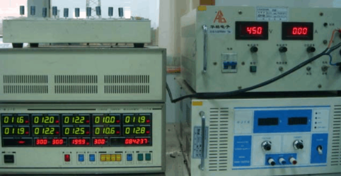
Testing
After the aging process is completed and the temperature of the electrolytic capacitor has decreased to room temperature, the pre-shipment testing of the electrolytic capacitor begins.
Testing
The testing of guide pin type electrolytic capacitors is conducted in the testing device of an automatic high-temperature aging machine, which can detect and classify short circuits, negative capacitance, excessive loss factor, and excessive leakage current for elimination.
Use a high-temperature aging box to age needle-type electrolytic capacitors, plug-in electrolytic capacitors, or bolt-type electrolytic capacitors, and then test them on the electrolytic capacitor testing system and eliminate defective products.