
Quite often referred to as a cap. Formerly known (primarily in the United Kingdom) as a condenser, but that term has become obsolete.
What It Does
A capacitor connected across a DC power source will accumulate a charge, which then persists after the source is disconnected. In this way, the capacitor stores(and can then discharge)energy like a small rechargeable battery. The charge/discharge rate is extremely fast but can be limited by a series resistor, which enables the capacitor to be used as a timing component in many electrolytic circuits.
A capacitor can also be used to block DC current while it passes pulses, or electrical “noise,” or alternating current,or audio signals, or other wave forms. This capability enables it to smooth the output voltage provided by power supplies.
To remove spikes from signals that would otherwise tend to cause spurious triggering of components in digital circuits; to adjust the frequency response of an audio circuit; or to couple separate components or circuit elements that must be protected from transmission of DC current.
Schematic symbols for capacitors are shown as follows.. At top-left is a non-polarized capacitor, while the other two indicate that a polarized capacitor must be used,and must be oriented as shown.
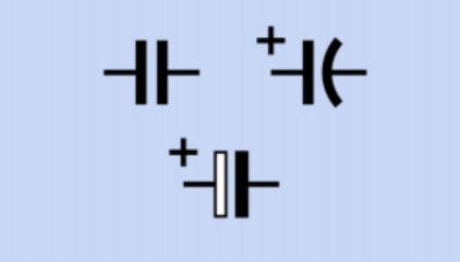
Schematic symbols for polarized and non-polarized capacitors. See text for details.
The variant at the bottom is most commonly used in Europe. Confusingly, the non-polarized symbol may also be used to identify a polarized capacitor, if a + sign is added. The polarized symbols are sometimes printed without + signs, but the symbols still indicate that polarity must be observed.
How It Works
The plates in most capacitors are made from thin metal film or metallized plastic film. To minimize the size of the component, the film may be rolled up to form a compact cylindrical package, or multiple flat sections may be interleaved.
Electrons from the power source will migrate onto the plate attached to the negative side of the source, and will tend to repel electrons from the other plate. This may be thought of as creating electron holes in the other plate or as attracting positive charges.
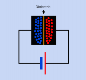
Because the plates of a capacitor are electrically conductive, they will become populated with positive and negative charges when connected with a DC power source.
Because the plates of a capacitor are electrically conductive, they will become populated with positive and negative charges when connected with a DC power source. As opposite charges attract each other,they will tend to congregate on either side of the dielectric, which is an insulating layer. The battery symbol is shown here colored for clarity.
When the capacitor is disconnected from the power source, the opposite charges on its plates will persist in equilibrium as a result of their mutual attraction, although the voltage will gradually dissipate as a result of leakage,either through the dielectric or via other pathways.
When a resistor is placed across the leads of a charged capacitor, the capacitor will discharge itself through the resistor at a rate limited by the resistance. Conversely, if a capacitor is charged through a resistor,the resist or will limit the charging rate.
A resistor in series with a capacitor is known as an RC network (Resistor-Capacitor network). In Figure , an RC circuit is shown with a SPDT switch that charges or discharges the capacitor via a series resistor. The voltage at point A increases non-linearly (relative to the negative side of the power supply) while the capacitor is charging, and decreases non-linearly while the capacitor is discharging, as suggested by the graphs.
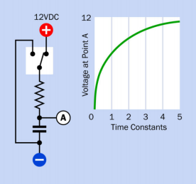
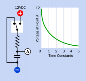
An RC (Resistor-Capacitor) network with a switch to control charge and discharge of a capacitor.
At any moment, the time that the capacitor takes to acquire 63% of the difference between its current charge and the voltage being supplied to it is known as the time constant for the circuit.
When a capacitor is connected across an AC voltage source, each surge of electrons to one plate induces an equal and opposite positive surge to the other plate, and when polarity of the power supply reverses, the charges on the plates switch places. These surges may make it seem that the capacitor is conducting AC current, even though the dielectric that separates the plates is an insulator.
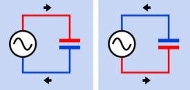
In the left diagram, a source of alternating current charges the upper plate of a capacitor positively and the lower plate negatively. This process entails a flow of conventional current shown by the arrows. A moment later, when the AC current flow reverses, the flow also reverses, creating the impression that the capacitor “passes” AC current.
Often a capacitor is said to “pass” AC, even though this is not really happening. For convenience, and because the concept is widely established, this article refers to capacitors as “passing” AC.
Depending on the size of the capacitor, it will block some AC frequencies while passing others. Generally speaking, a smaller capacitor will pass high frequencies relatively efficiently, as each little surge of current fills each plate. However, the situation is complicated by the inductive reactance (which creates the effective series resistance) of a capacitor.
Variants
Format
The three most common packages for capacitors are cylindrical, disc, and rectangular tablet.
A cylindrical capacitor may have axial leads (a wire attached to each end) or radial leads (both wires emerging from one end). Radial capacitors are more widely used as they allow easy insertion into a circuit board. The capacitor is usually packaged in a small aluminum can, closed at one end, capped with an insulating disc at the other end, and wrapped in a thin layer of insulating plastic. Some samples are shown in Figure .
Cylindrical capacitors with radial leads. All are electrolytic.
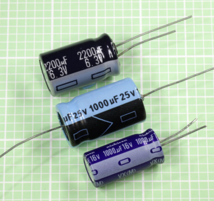
Cylindrical capacitors with radial leads (top and bottom) and axial leads (center). All are electrolytic.
A disc capacitor (sometimes referred to as a button capacitor) is usually encased in an insulating ceramic compound, and has radial leads. Modern small-value ceramic capacitors are more likely to be dipped in epoxy, or to be square tablets. Some samples are shown in Figure.
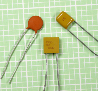
Generic ceramic capacitors. Left: rated for 0.1μF at 50V. Center: 1μF at 50V. Right: 1μF at 50V
A surface-mount capacitor is square or rectangular, usually a few millimeters in each dimension, with two conductive pads or contacts at opposite ends. It appears almost identical to a surface-mount resistor. Larger-value capacitors are inevitably bigger but can still be designed for surface-mount applications.

Most surface-mount capacitors are as tiny as other surface-mount components, but this 4,700μF electrolytic (at 10V) has a base approximately 0.6” square.A solder tab is visible at the center of the nearest edge.
Many capacitors are nonpolarized, meaning that they are insensitive to polarity. However, electrolytic and tantalum capacitors must be connected “the right way around” to any DC voltage source. If one lead is longer than the other, it must be the “more positive” lead.
A mark or band at one end of the capacitor indicates the “more negative” end. Tantalum capacitors are likely to indicate the positive lead by using a + sign on the body of the component.
An arrow printed on the side of a capacitor usually points to the “more negative” terminal. In an aluminum can with axial leads, the lead at one end will have an insulating disc around it while the other lead will be integral with the rounded end of the can. The wire at the insulated end must be “more positive” than the wire at the other end.
A capacitor array contains two or more capacitors that are isolated from each other internally and accessed by external contacts. They are sold in surface-mount format and also in through-hole chips of DIP (dual-inline package) or SIP (single-inline package) format.
The internal components may be connected in one of three configurations: isolated, common-bus, or dual-ended common bus. Technically the isolated configuration should be referred to as a capacitor array, but in practice, all three configurations are usually referred to as capacitor networks.
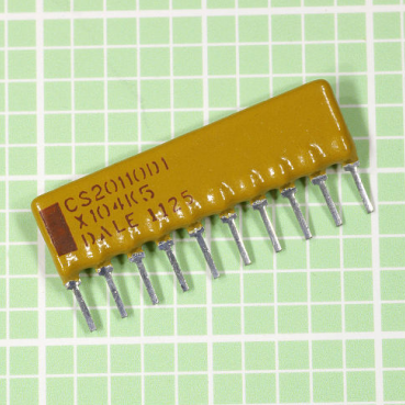
A capacitor array in through-hole, SIP for-mat.
Capacitor networks can reduce the component count in circuits where digital logic chips-require bypass capacitors. They are comparable in concept to resistor arrays.
Chips containing RC circuits (multiple resistor-capacitor pairs) are available, although uncommon.
Principal Types
Electrolytic capacitors are relatively cheap, compact, and available in large values. These attributes have made them a popular choice in consumer electronics, especially for power supplies. The capacitive capability of an electrolytic is refreshed by periodic application of voltage.
A moist paste inside the capacitor is intended to improve the dielectric performance when voltage is applied, but can dry out during a period of years. If an electrolytic is stored for 10 years or so, it may allow a short circuit between its leads when power is applied to it. The capacitor in Figure is at the high end of the scale.
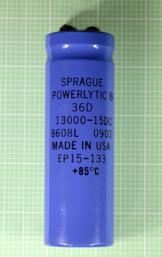
This 13,000μF electrolytic capacitor is larger than would be required in most everyday applications.
A bipolar electrolytic is a single package containing two electrolytic capacitors in series, end-to-end, with opposed polarities, so that the combination can be used where the voltage of a signal fluctuates above and below 0VDC.
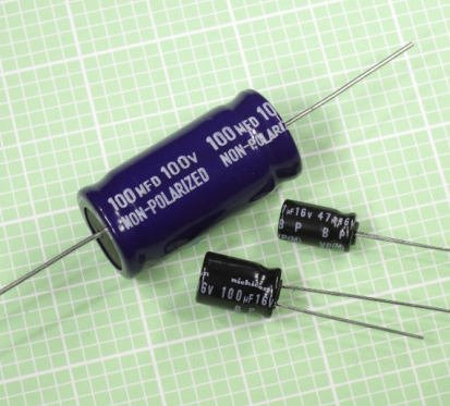
Bipolar electrolytic capacitors. The larger size of the one at top-left is a consequence of its higher voltage rating. “BP” on the other two capacitors is an acronym for “bipolar,” meaning that they have no polarity, even though one lead may be shorter than the other.
This type of component is likely to have “BP” (bipolar) or “NP”(non-polarized) printed on its shell. It may be used in audio circuits where polarized capacitors are normally unsuitable, and is likely to be cheaper than non-electrolytic alternatives. However, it suffers from the same weaknesses as all electrolytics.
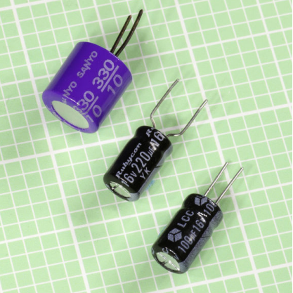
Tantalum capacitors are compact but relatively expensive, and can be vulnerable to voltage spikes. They are sensitive to application of the wrong polarity. Typically they are epoxy-dipped rather than mounted inside a small aluminum can like electrolytics, and consequently the electrolyte may be less likely to evaporate and dry out.
In Figure, two tantalum capacitors (rated 330μF at 6.3V, left, and 100μF at 20V, right) are shown above a polyester film capacitor (rated 10μF at 100V). Surface-mount tantalum capacitors are decreasing in popularity as large-value ceramic capacitors are becoming available, with smaller dimensions and lower equivalent series resistance.
Two tantalum capacitors are shown above a polyester film capacitor. The polarity of the tantalum capacitors is indicated by the plus signs adjacent to the longer lead, in each case. The polyester capacitor is non-polarized.
Single-layer ceramic capacitors are often used for bypass, and are suitable for high-frequency or audio applications. Their value is not very stable with temperature, although the “NPO” variants are more stable.
Multilayer ceramic capacitors are more compact than single-layer ceramic, and consequently are becoming increasingly popular. Three multilayer ceramic capacitors are shown in Figure. At bottom-right, even the largest (rated at 47μF at 16V) is only “0.2” square.

Multi-layer ceramic capacitors are extremely compact, and are non-polarized. Top: 1,000pF (i.e. 1nF) at 100V. Bottom left: 1μF at 25V. Bottom right: 47μF at 16V.
Dielectrics
The dielectric used in a capacitor most often consists of an electrolytic layer, a ceramic compound, a plastic film (poly-carbonate, polypropylene, or polystyrene), or paper.
An electrolytic layer in an electrolytic capacitor traditionally consists of paper soaked in an electrolyte. It is interleaved with a thin film of aluminum on which is deposited a layer of aluminum oxide. The layers are rolled up to create a cylindrical component. The functioning dielectric is created when voltage is applied.
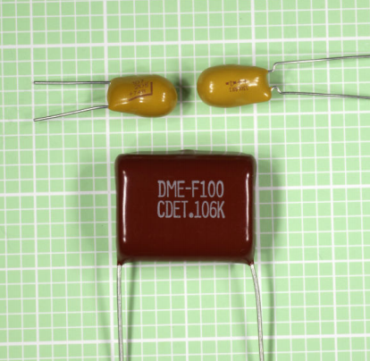
Polyester
This is the most common type of plastic film, with the highest dielectric constant, enabling highest capacitance per unit volume. Widely used in DC applications, but the rolled layers create parasitic inductance. Often used in decoupling, coupling, and bypass, but not so suitable for situations requiring stability and low leakage. May not be suitable for high current.
Poly-carbonate
Thermally very stable, often specified for filters and timing circuits that require a fixed
frequency. An excellent type of capacitor,compatible for mil-spec applications, but expensive.
Mylar, Polyester, and other plastic-film types are often used in audio circuits, where their voltage limitation (typically less than 100VDC) is not a problem, and their non-polarized attribute is an advantage.
Polypropylene
Vulnerable to heat (a maximum of 85 degrees Centigrade is common), and less thermally stable than poly-carbonate. A very low power dissipation factor allows it to handle higher power at higher frequencies. Available with tolerances down to 1%. These capacitors are a popular choice in crossover networks for loudspeaker combinations, and are used in switching power supplies. They tend to be physically larger than other capacitors using film dielectric.
Values
Farads
The electrical storage capacity of a capacitor is measured in farads, universally represented by the letter F. A capacitor that can be charged with a potential difference between its plates of 1 volt, in a time of 1 second, during which it draws 1 amp, has a capacitance of 1 farad.
Because the farad is a large unit, capacitors in electronic circuits almost always have fractional values: micro-farads (μF), nano-farads (nF), and picofarads (pF). The Greek letter μ (mu) should be used in the μF abbreviation, but a lowercase letter u is often substituted. Thus, for example, 10uF means the same as 10μF.
1F = 1,000,000μF, and 1μF = 1,000,000pF. Therefore, 1 farad is equivalent to 1 trillion picofarads—a very wide range of possible values. See Figure for charts showing equivalent values in different units.
| pF | nF | μF |
| 1 | 0.001 | 0.000001 |
| 10 | 0.01 | 0.00001 |
| 100 | 0.1 | 0.0001 |
| 1000 | 1 | 0.001 |
| 10000 | 10 | 0.01 |
| 100000 | 100 | 0.1 |
| 1000000 | 1000 | 1 |
Equivalent values for picofards, nanoseconds, and micro-farads. The nF unit is used primarily in Europe.
| μF | F |
| 1 | 0.000001 |
| 10 | 0.00001 |
| 100 | 0.0001 |
| 1000 | 0.001 |
| 10000 | 0.01 |
| 100000 | 0.1 |
| 1000000 | 1 |
Equivalent values for micro-farads and farads. Because the farad is such a large unit, electronic circuits almost always use fractional values.
The nF unit is more common in Europe than in the United States. A 1nF capacitance is often expressed in the US as 0.001μF or 1,000pF. Similarly, a 10nF capacitance is almost always expressed as a 0.01μF, and a 0.1nF capacitance is more likely to be expressed as 100pF.
European schematics may use value-symbols as a substitute for decimal points. For example, a 4.7pF capacitor may be shown as 4p7, a 6.8nF capacitor may be shown as 6n8, and a 3.3μF capacitor may be shown as 3μ3.
Commonly Used Values
The traditional range of capacitor values was established on the same basis as the traditional range of resistor values, by assuming an accuracy of plus-or-minus 20% and choosing factors that would minimize the possible overlap between adjacent tolerance ranges. The factors 1.0, 1.5, 2.2, 3.3, 4.7, 6.8, and 10 satisfy this requirement.
While many resistors are now manufactured with high precision, 20% tolerance is still common for electrolytic capacitors. Other types of capacitors are available with an accuracy of 10% or 5%, but are more expensive.
While large-value capacitors are likely to have their actual value printed on them, smaller capacitors are identified by a variety of different codes. These codes are not standardized among manufacturers, and exist in various colors and abbreviations. A multi-meter that can measure capacitance is a quicker, easier, and more reliable method of determining the value of a component than trying to interpret the codes.
In addition to capacitance, a large capacitor is likely to have its working voltage printed on it. Exceeding this value increases the risk of damaging the dielectric. In the case of electrolytic capacitors, a voltage that is much lower than the rated value should also be avoided, because these capacitors require an electrical potential to maintain their performance.
In common electronics applications, values larger than 4,700μF or smaller than 10pF are unusual.
Electrolytics are available at a moderate price in a wider range of values than other commonly used capacitors. They range from 1μF to 4,700μF and sometimes beyond. Working voltages typically range from 6.3VDC to 100VDC, but can be as high as 450VDC.
Tantalum capacitors are usually unavailable in sizes above 150μF or for voltages above 35VDC.
Single-layer ceramic capacitors have small values ranging from 0.01μF to 0.22μF, with working voltages usually not exceeding 50VDC, although very small-value capacitors may be rated much higher for special applications. Poor tolerances of +80% to -20% are common.
Some variants of multi-layer ceramic capacitors are capable of storing up to 47μF, although 10μF is a more common upper limit. They are seldom rated above 100VDC. Some are accurate to plus-or-minus 5%.
Dielectric Constant
If A is the area of each plate in a capacitor (measured in square centimeters), and T is the thickness of the dielectric (measured in centimeters), and K is the dielectric constant of the capacitor, the capacitance, C (measured in farads) will be obtained from the formula:
C = (0.0885 * K * A) / T
The dielectric constant of air is 1. Other dielectrics have different standard values. Polyethylene, for instance, has a constant of approximately 2.3. Thus a capacitor of 1 square centimeter plate area and polyethylene dielectric 0.01 centimeters thick would have a capacitance of about 20pF.
A tantalum capacitor of equal plate area and dielectric thickness would have capacitance closer to 100pF, since the dielectric constant of tantalum oxide is much higher than that of polyethylene.
The Time Constant
When a capacitor is charged in series through a resistor (it is used in an RC network), and it begins with no charge on its plates, the time constant is the time, in seconds, required to charge the capacitor to 63% of the supply voltage. After an additional, identical interval of time, the capacitor will acquire 63% of the remaining difference between itself and the power supply.
In theory the capacitor gets closer and closer to a full charge, but never quite reaches 100%. However, five time constants are sufficient for the capacitor to reach 99%, which is regarded as close enough to being fully charged for all practical purposes.
The time constant is a simple function of the resistance and the capacitance. If R is the value of the resistor (in ohms), and C is the value of the capacitor (in farads), the time constant, TC, will be obtained by the formula:
TC = R * C
If we multiply the R value by 1,000 while dividing the C value by 1,000, the time constant remains the same, and we can use the more convenient values of kilohms for the resistance and μF for the capacitance. In other words, the formula tells us that a 1K resistor in series with a 1,000μF capacitor has a time constant of 1 second.
The formula suggests that if the value of R diminishes to zero, the capacitor will charge instantly. In reality, the charging time will be rapid but finite, limited by factors such as the electrical resistance of the materials used.
Multiple Capacitors
When two or more capacitors are wired in parallel, their total capacitance is the sum of their separate capacitances. When two or more capacitors are wired in series, the relationship between their total capacitance C and their individual capacitances (C1, C2, C3 . . .) is given by this formula:
1 / C = (1/C1) + (1/C2) + (1/C3). . .
The formula to calculate the total capacitance of capacitors connected in series resembles the one used to calculate the total resistance of resistors connected in parallel.
Alternating Current and Capacitive Reactance
The apparent resistance of a capacitor to AC is properly known as capacitive reactance. In the following formula, capacitive reactance (XC, in ohms) is derived as a function of capacitance (C, in farads) and AC frequency (f, measured in hertz):
XC = 1 / (2 * π * f * C)
The formula shows that when frequency becomes zero, capacitive reactance becomes infinite; in other words, a capacitor has theoretically infinite resistance when DC current tries to flow through it. In reality, a dielectric has a finite resistance, and thus always allows some leakage.
The formula also shows that capacitive reactance diminishes when the size of the capacitor increases and/or the frequency being applied to it increases. From this it appears that an AC signal will be attenuated less at higher frequencies, especially if we use a small capacitor.
However, a real-world capacitor also exhibits some degree of inductive reactance. This value will depend on its configuration (cylindrical vs. multiple flat plates), its physical length, the materials from which it is fabricated, the lengths of its leads, and other factors.
Inductive reactance tends to increase with frequency, and since capacitive reactance tends to decrease with frequency, at some point the curves for the two functions intersect. This point represents the capacitor’s self-resonant frequency, which is often referred to simply as its resonant frequency.
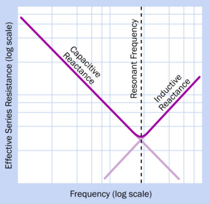
As an AC current applied to a capacitor increases in frequency, the capacitive reactance of the component decreases, while its inductive reactance increases. The resonant frequency of the capacitor is found where the two functions intersect.
Equivalent Series Resistance
A theoretically ideal capacitor would be purely reactive, without any resistance. In reality, capacitors are not ideal, and they have equivalent series resistance, or ESR. This is defined as the resistor that you would have to place in series with an ideal version of the capacitor, so that the combination would behave like the real version of the capacitor on its own.
If Xc is the reactance of the capacitor, then its Q factor (which means its quality factor) is given by the simple formula:
Q = Xc / ESR
Thus, the quality factor is higher if the ESR is relatively low. However, the reactance of the capacitor will vary significantly with frequency, and this simple formula is only an approximate guide.
The Q-factor for capacitors should not be confused with the Q-factor for inductors, which is calculated quite differently.
How to Use it
The figures illustrate some simplified schematics for common applications.
Bypass Capacitor
In Figure , a low-value capacitor (often 0.1μF) is placed near the power input pin of a sensitive digital chip to divert high-frequency spikes or noise to negative ground. This bypass capacitor may also be described as a decoupling capacitor.
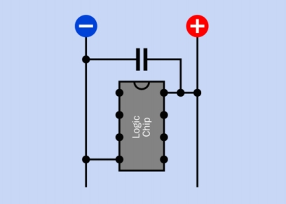
A bypass capacitor (typically 0.1μF) configured to protect an integrated circuit logic chip from voltage spikes and noise in the power supply
Coupling Capacitor
In Figure , a 1μF coupling capacitor transmits a pulse from one section of a circuit to another, while blocking the DC voltage. Some reshaping of the waveform may occur.
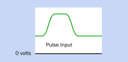
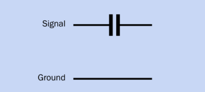
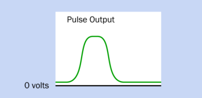
A coupling capacitor (typically around 1μF) preserves DC isolation of one section of a circuit from another, while allowing a pulse to be transmitted.
High-Pass Filter
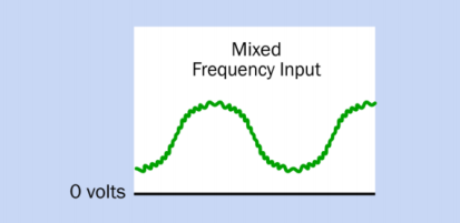
In Figure , a 0.1μF capacitor blocks the low-frequency component of a complex waveform
and transmits only the higher frequency that was superimposed on the low frequency.
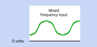
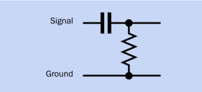
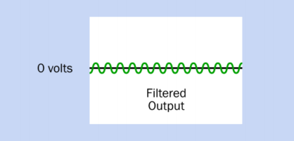
A small capacitor (typically 0.1μF) can be used to create a high-pass filter, passing high frequencies while blocking low frequencies.
Low-Pass Filter
In Figure , a 0.1μF decoupling capacitor diverts the higher frequency component of a complex waveform to negative ground, allowing only the lower frequency to be preserved. A lower-value capacitor (such as 0.001μF) will bleed away-high-frequency noise from an AM radio source without affecting audio frequencies.
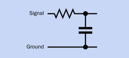
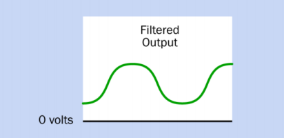
A small capacitor (typically 0.1μF) in this configuration routes high frequencies to negative ground, filtering them out of an analog signal.
Smoothing Capacitor
In Figure , a 100μF capacitor charges and discharges to smooth an AC signal after a diode has removed the negative portion.
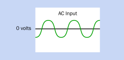
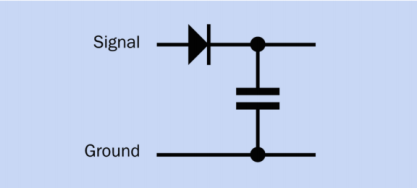
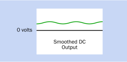
A capacitor of 100μF or more smooths the upper half of an AC signal that has passed through a diode. The capacitor charges during each positive pulse and discharges to “fill the gaps” between them.
Snubber
In Figure , an RC network (inside a white dashed line) is known as a snubber when used to protect a switch from the problem of arcing (pronounced “arking”)—that is, a sustained spark that can quickly erode the switch contacts.
Arcing may occur in switches, push-buttons, or relays that control an inductive load, such as a large motor. This problem can become significant at high DC currents (10A or more) or relatively high AC or DC voltages (100V or more).
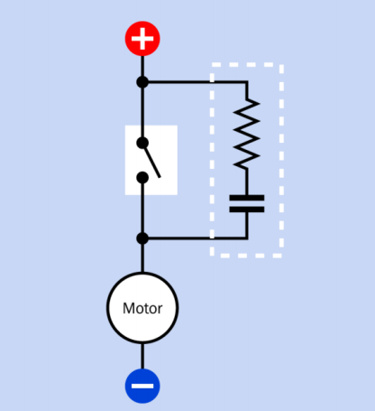
An RC network (outlined with a white dashed line) protects a switch that controls a high inductive load. Used in this way the RC network is known as a snubber.
When the switch is opened, the magnetic field that has been sustained by the inductive load collapses, causing a surge of current, or forward EMF. The capacitor in the snubber absorbs this surge, thus protecting the switch contacts. When the switch is closed again, the capacitor discharges itself, but the resistor limits the out-rush of current—again, protecting the switch.
A snubber placed around the switch in a DC circuit could typically use a 0.1μF capacitor (polypropylene or polyester) rated for 125VAC/200VDC, and a 100-ohm carbon resistor rated 0.5 watt or higher. Prepackaged snubbers containing appropriate capacitor-resistor pairs are available from some parts suppliers, primarily for industrial use.
In an AC circuit, a snubber can be placed around the inductive load itself. Although a diode is often used this way in a DC circuit, it cannot be used with AC.
Although solid-state switching devices such as a solid state relay contain no mechanical contacts, they may still be damaged by substantial pulses of back-EMF, and can be protected by a snubber where they are controlling inductive loads that take 10A or more at 100V or more.
Capacitor as a Battery Substitute
A capacitor may be substituted for a battery for some applications, although it has a lower energy density and will be more expensive to manufacture. A capacitor charges and discharges much more rapidly than a battery because no chemical reactions are involved, but a battery sustains its voltage much more successfully during the discharge cycle.
Capacitors that can store a very large amount of energy are often referred to as super-capacitors.
What Can Go Wrong
Common problems associated with capacitors are age-related deterioration (especially in electrolytics), inductive reactance (especially in cylindrical formats), nonlinear response, resistivity, excessive current leakage, and dielectric memory. Some of these problems are discussed below.
A manufacturer’s datasheet should be consulted carefully in conjunction with the notes regarding compositions in the preceding Variants section before making a commitment to a particular type of capacitor.
Wrong Polarity
A polarized capacitor may offer virtually no resistance if it is connected the wrong way around to a DC power source. A very high current can result, damaging the capacitor and probably other components in the circuit. Failing to observe the polarity of a tantalum capacitor can have destructive or even explosive consequences, depending on the amperage.
Voltage Overload
If the DC working voltage of a capacitor is exceeded, there is a risk of breaking down the dielectric and allowing a spark, or arc, that will form a short circuit. Note that the DC rating of a capacitor does not mean that it can be used safely with an equivalent AC voltage.
The maximum AC voltage should be no greater than approximately 0.7 times the DC rated voltage. If a DC-rated capacitor is used directly across an AC power line, it will create an effective short circuit.
If capacitors are connected in series or in parallel, ideally the voltage rating for each capacitor should be the same, and certainly no less than the supply voltage.
Tantalum capacitors are easily damaged by current spikes that exceed their maximum working voltage, and are unsuitable for high-frequency coupling because of their inductance.
Leakage
Charge leakage is a problem especially associated with electrolytic capacitors, which are not suitable for storing a charge over a significant interval. Polypropalene or polystyrene film capacitors are a better choice.
Dielectric Memory
Also known as dielectric absorption, this is a phenomenon in which a capacitor’s electrolyte displays some percentage of its former voltage after the capacitor has been discharged and then disconnected from the circuit. Single-layer ceramic capacitors especially tend to suffer from this problem.
Specific Electrolytic Issues
Electrolytic capacitors have high inductive reactance, are not manufactured to close tolerances, and deteriorate significantly with age. While other components may be stockpiled and used over a period of years, this is not a sensible policy with electrolytics.
The “capacitor plague” affecting many of these capacitors manufactured from 1999 onward provided a salutary lesson regarding their potential weaknesses. Faulty composition of the dielectric allowed it to deteriorate, liberating hydrogen gas, which eventually caused the aluminum shells of the capacitors to bulge and burst.
Circuit boards from major manufacturers were affected. Because the problem took two years to become apparent, literally millions of boards with faulty capacitors had been sold before the fault was diagnosed and eventually corrected.
Unfortunately electrolytics cannot be easily replaced with other types of capacitors in applications such as power supplies, because substitutes will be considerably larger and more expensive.
Heat
The equivalent series resistance (ESR) of a large capacitor inevitably means that it must dissipate some power as heat during use. Ripple current can also create heat. Capacitor performance will change as the temperature increases. A common maximum component temperature for electrolytic capacitors is 85 degrees Centigrade.
Vibration
In a high-vibration environment, electrolytics should be protected by clamping them mechanically in place, using a capacitor clamp, also known as a c-clamp.
Misleading Nomenclature
Rarely, in the United States, the term “mF” may be used as a probable alternative to μF. This can be a source of confusion and risk because mF is properly (but very rarely) used to mean “millifarads.” The term should always be avoided.