Aluminium electrolytic capacitors are characterized by the following components:
- Anode: aluminium – etched and formed aluminium foil/mechanically formed shapes
- Electrolyte: solid/liquid /paste chemicals – Act as de facto cathode terminal
- Kraft or manila paper as electrolyte carrier
- Dielectric: oxide layer film on anode
- Cathode: etched foil/can – serves mainly as current collector from electrolyte.
- Connection leads: tabs
- Terminal disc – This is generally rubber bonded bakelite disc.
- Pressure vent – either built up in disc, or as separate plug. Generally in small DC capacitors,the can bottom is grooved to crack open in case of failure.
Aluminium has been used in electrolytics on account of its flexibility in use, etching, electrode formation, winding, and cost. All electrolytics are essentially polar in nature, and the polarity cannot be reversed.
The capacitor acts as a short circuit if polarity of applied voltage is reversed. AC electrolytics are in fact two electrolytics connected in series back to back. One capacitor works in any given polarity while the other is a short circuit.
Aluminium electrolytics do not have competition from tantalum or other capacitors in highervoltages as other electrolytics are essentially for low voltage applications. Even in low voltage,they have the advantage of lower cost per unit.
There are basically two types of Aluminium electrolytic capacitor, the plain foil type and the etched foil type. The thin aluminium oxide film dielectric and high breakdown voltage give these capacitors very high capacitance values.
In etched foil type the aluminium oxide on the anode and cathode foils are chemically etched to increase its surface area and permittivity. However, plain foil type has the advantage of higher AC current capacity.
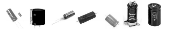
Aluminium electrolytic capacitors of various types.
Tolerance range of the common etched type is quite large, up to 20%. They find use in coupling, DC blocking and bypass circuits. Plain foil types are better suited as smoothing capacitors in power supplies.
Typical values of capacitance range from 1 μF to 47000 μF. Aluminium electrolytics are polar in nature and reversing the applied voltage on the leads will destroy the capacitor.
Motor Start Electrolytic Capacitor
These are basically two DC electrolytic capacitors connected back-to-back. One capacitor bears the voltage in positive half cycle, while the other acts as a short circuit. The reverse occurs in negative half cycle. The loss factor being very high, of the order of 1.8% to 7%, depending upon design and local standards governing them, the heat generation is considerable.
The capacitor gets heated up very fast, which limits the time it can remain in circuit. The usual duty for this capacitor is 3 s on, and 177 s off, or 1.7% of the time cycle permissible within this overall maximum limit. A centrifugal switch on the motor shaft cuts off the auxiliary winding circuit and with it thecapacitor, once the motor achieves a predetermined speed.
A motor start capacitor of 250 μF capacitor at 230 V RMS carries a current of about 18 amp, which works out to 4140 VA, and a loss factor of 5% leads to heat loss of 200 W. If not switched off during the decided time limit, the heat generated can cause the capacitor to explode violently.
To ward off this eventuality, a pressure vent is normally provided on the cover for safety, which blows off to allow the products of heat generation – air and vapours –to escape safely. The capacitor is then rendered out of service, and has to be replaced.
The external electrodes of motor start capacitor are connected to etched and formed anode foils (formed to a suitable voltage by the supplier), and interleaved by layers of electrolytic capacitor paper.
The paper is of low density, its function being to retain the electrolyte in contact with the foils, as also to act as separator. The thickness, type of paper (kraft/manila), and the number of papers is decided by the desired properties and electrolyte used.
Sometimes a common cathode foil is used to physically form two internal capacitors in series, the cathode being common to both capacitor sections. The cathode is not connected to any terminal, but is a floating electrode.
The cathode and the additional volume on this account serve as thermal storage and reduction of loss factor. The voltage withstand time of capacitor at rated voltage is also better in this design. The cost, though, is higher.
Motor start capacitors are available in different configurations, like single can insulated body (in heat shrinkable sleeve insulation), double can aluminium can with wire, double can with terminals in insulated body etc.
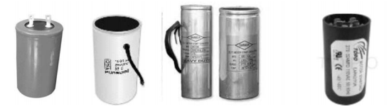
Motor start electrolytic capacitors.
The voltage withstand time at rated voltage is frequently used to determine capacitor quality,and to see in-built safety limit. In many countries a time to burst the seal at rated voltage is considered satisfactory if it exceeds three minutes. Five minutes is considered by most to be among the best.
Ratings of motor start capacitors
Ratings of capacitors are in wide tolerance limits (electrolytic capacitors cannot be made to close tolerances as electrostatic ones). Motor start capacitors in India are rated at 230 V AC nominal, with surge voltage of 275 V AC (25% over-voltage).
Capacitance ratings commonly in vogue are: 40–60 μF, 60–80 μF, 80–100 μF, 100–120 μF, 120–150 μF, 150–200 μF and 200–250 μF. Even much higher ratings are being made on demand. The rated power factor is below 8%.
In most cases, the power factor is under 5%, with best construction giving a power factor of as low as 1.8%. The duty cycle is specified as 3 s on, followed by 177 s off, and a maximum of 20 starts per hour. This is sometimes mentioned as 1.7% duty cycle.
Testing of motor start capacitors
Motor start capacitors are subjected to the following routine tests at the final testing stage:
- Capacitance value
- Surge voltage
- Power factor
- AC high voltage test between shorted terminals and container
Type tests include the following:
- Charge–discharge cycle at 230 V AC at rated duty cycle, viz. 3 s on, followed by 177 s off. The endurance test is carried at rated capacitor temperature, and for 10,000 operations.
- Vent burst time: The time taken by the vent to burst is an indication of capacitor quality. A time of 3–5 min is targeted by different manufacturers: the longer the time, the better it is. At the end of the expected burst time, the rubber vent or plug should burst, giving way to gases formed inside due to overheating in this prolonged period. This is also a safety test for the capacitor, which should not explode during the test.
Metallized Motor Start Capacitors
While talking of motor start capacitors, it is pertinent to mention a new development recently which enables the use of metallized film capacitors for motor start applications. The film is very thin MPP or MPET, below 5 microns, and capacitor size is comparable to electrolytic capacitors.
The cost is comparable, while the reliability is impeccable. Loss factor of these capacitors is under 0.5% for MPET, or 0.05% for MPP. The capacitors successfully withstand 250 V AC for over 30 min without failure, and do not fail up to 10 min at 275 V AC.
They can be made to close tolerances of 5%, as against very wide tolerance limits for electrolytics. Failure rate of capacitors due to failure of centrifugal switch within a specified short time also goes down.
The use of metallized capacitors for motor start application opens up the possibility of making full use of enhanced voltage capacity by redesigning the motor to reduce copper in motor winding, and making the whole exercise cost effective.
The capacitor being self-healing, the life is also improved. Electrolytic capacitors, by their nature, have a limited life expectancy compared with electrostatic types.
Energy Storage Electrolytic Capacitors
One of the main applications of aluminium electrolytic capacitors is as input capacitors for power inverters. The aluminium electrolytic capacitor provides a unique value in high-energy storage and low device impedance.
Selecting the right capacitor for an application requires knowledge of all aspects of the application environment, from mechanical to thermal to electrical. These capacitors routinely offer capacitance values up to 3 F and voltage ratings from 5 V to 500 V.
Some possibilities include
- 330 μF at 100 V and 6800 μF at 10 V for SMT devices,
- 100 μF at 450 V, 6800 μF at 50 V and 10,000 μF at 10 V for miniature-can styles,
- 1200 μF at 450 V and 39,000 μF at 50 V for snap-in can styles,
- 9000 μF at 450 V and 390,000 μF at 50 V for large-can, screw-terminal styles.
They are polar devices, having distinct positive and negative terminals, and are offered in an enormous variety of styles which include moulded and can-style SMT devices, axial- and radial- leaded can styles, snap-in terminals styles and large-can, screw terminal styles.
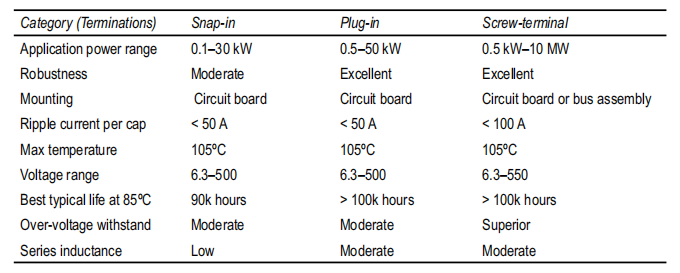
Mounting can be normal style or stud mount. The following data from a manufacturer will give an idea of power available from these three configurations of capacitors:
Power Available from Electrolytic Capacitor
These capacitors are used in large inverter power supplies everywhere, and on most naval vessels. Flashlight cameras and professional flashlights also make use of aluminium electrolytics from 15 μF to 1500 μF and voltage ratings from 300 V to 600 V for energy storage for flash. Flashgun capacitors typically store energy from 15 joules upwards up to 600 joules or more.
Limitations Of Electrolytic Capacitors
The disadvantage of electrolytic capacitors is the non-ideal, high loss characteristics which arise from the semi-conductive oxide properties, double-layer effects from the electrolyte-oxide charge-space region, resistive losses from the high electrolyte resistivity, poor frequency response due to the roughness of the surface oxide, and finite capacitor life due to breakdown and degradation of the electrolyte.
The anodic oxide dielectric is polar, and so are the electrolytic capacitors; that means the capacitors must be connected with the correct polarity as marked. Connecting with reverse voltage injects hydrogen ions through the oxide readily, causing high electrical conduction, heating and reduction of the anodic oxide film.
Non-polar (or bi-polar) devices can be made by using two anodes instead of an anode and a cathode, or one could connect the positives or negatives of two identical devices together, then the other two terminals would form a non-polar device.
Aluminium electrolytic capacitors can withstand reverse voltages up to 1.5 V. Higher reverse voltage can cause failure by pressure build-up and rupture of the capacitor’s safety vent structure. Non-polar and semi-polar devices are available that can withstand reverse voltage.
Safety Considerations
During operation of an aluminium electrolytic capacitor with non-solid electrolyte, gas pressure normally increases. This gas is mostly hydrogen and excess pressure is avoided by permeation of the gas through the capacitor’s seal.
But in cases like application of over-voltage, reverse voltage, AC voltage, capacitor failure or excess pressure can cause the capacitor to explode. To reduce the risk of explosion aluminium electrolytic capacitors are usually equipped with pressure-relief vent structures.
These safety vents are intended to rupture and release the gas pressure. After rupture the capacitor has limited life because it loses the electrolyte and dries out. One should be careful not to interfere with the operation of the vent, for instance by mounting measures such as clamps, glue or potting compounds.
In the case of large capacitors with internal cans secured by thermoplastic potting, they should not be mounted with the safety vents down as the potting may flow when the capacitors overheat and block the vents.