
Basic principles
The capacitor is one of the three basic passive circuit components of any electronic or electrical circuit. Resistance in a circuit gives rise to oh-mic or watt losses, and its current is in phase with the applied voltage waveform. Inductance or a capacitance gives rise to currents out of phase with voltage by 90° in AC circuits, and is the cause of transient currents in many circuits.
Inductance is an electromagnetic activity, a basic principle behind all transformers, motors, pumps, electromagnets, chokes etc. It resists a change in current, and stores energy when carrying a current. An ideal inductor is a short circuit path to a steady DC current. In AC circuits, its current lags behind the voltage by 90°.
A capacitor on the other hand, works in electric field. Its properties are exactly opposite to those of inductance, i.e. it resists a change in voltage. It stores energy when a steady voltage is applied. It gets charged to the applied voltage and keeps the energy as well as the voltage even after removal of external voltage.
This factor makes handling of capacitors quite dangerous at times, and caution must be exercised when working with them. A capacitor offers an open circuit to the flow of DC current in steady state. Current in an ideal capacitor leads the voltage by 90° in AC circuits.
A capacitor is defined as two conductors (or sets of interconnected conductors) separated by a dielectric. The conductors may be plates, foil, solid shapes, or even wires. The separator can be air, vacuum, solids, an oxide layer on metal (as in electrolytic capacitors), flat thin paper or film, placed or wound on the conductors.
A pair of cables near each other will have a capacitance, however small. A capacitor is also formed on two sides of a PCB by coating metal on opposite sides of a given area.
Figure shows the general construction of a parallel plate capacitor. The plates shown maybe metal foil, or more commonly for many AC applications, the conductive surface of a metallized film.

Construction of a capacitor
This set of electrodes and dielectrics is very thin and typically long and narrow, which is rolled up and encapsulated. In some cases, the capacitor is made flat, with interleaved plates and dielectric. This allows maximum capacitance for a given volume.
Figure shows the general symbols used for capacitors.
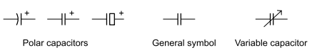
Symbols for capacitors
Electric field
It will be useful to dwell upon the electric field for a better understanding of capacitors. In physics, an electric field surrounds electrically charged particles and time-varying magnetic fields. The electric field strength at a point is the force per unit charge exerted on a positive charge placed at that point. This electric field exerts a force on other electrically charged objects.
The English chemist, Michael Faraday, introduced the concept of an electric field. All charged objects create an electric field that extends outward into the space that surrounds it. The charge alters that space, causing any other charged object that enters the space to be affected by this field. The strength of the electric field is dependent upon how charged the object creating the field is and upon the distance of separation from the charged objects.
Electric Field Strength = Force/Charge, or E = F/Q
A uniform electric field may be created by charging two plates. Increasing the voltage between them will increase the field strength, and moving the plates further apart will decrease the field strength. A simple equation for field strength appears as follows:
E = –V/d
Where V is the voltage between the plates, and d is the distance between them. The minus sign in the equation shows that the force that a positive charge will experience in the field is away from the positively charged plate.
An electric field being defined as a force per charge, its unit is force units divided by charge units, viz. newton/coulomb or N/C in metric units. The electric field is defined as the force per unit charge that would be experienced by a stationary point charge at a given location in the field.
E = F/q
Where F is the electric force experienced by the particle, q is its charge, and E is the electric field wherein the particle is located. Coulomb’s law states that the electric force between two charges is directly proportional to the product of their charges and inversely proportional to the square of the distance between their centres.
The electric field is a vector field with SI units of newtons per coulomb(NC-1)or, equivalently, volts per meter (Vm−1). The SI base units of the electric field are kg.m.s−3.A−1.The strength or magnitude of the field at a given point is defined as the force that would be exerted on a positive test charge of 1 coulomb placed at that point; the direction of the field is given by the direction of that force.
Electric fields contain electrical energy proportional to the square of the field amplitude. The electric field is to charge as gravitational acceleration is to mass and force density is to volume.
As is clear from the definition, the direction of the electric field is the same as the direction of the force it would exert on a positively charged particle, and opposite to the direction of the force on a negatively charged particle.
Since like charges repel and opposites attract, the electric field tends to point away from positive charges and towards negative charges. The fields created by a charged sheet and a spherical body are depicted in Figure.
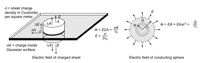
Electric fields of a sheet and sphere
Electric flux Ø is a measure of the number of electric field lines passing through an area. To calculate the flux through a particular surface, multiply the surface area by the component of the electric field perpendicular to the surface. If the electric field is parallel to the surface, no field lines pass through the surface and the flux will be zero. The maximum flux occurs when the field is perpendicular to the surface.
Oppositely charged parallel conducting plates may be treated like infinite planes (neglecting fringing), and Gauss’ law used to calculate the electric field between the plates. Presuming the plates to be at equilibrium with zero electric field inside the conductors, then the result from a charged conducting surface can be used:
The energy density of the electric field is given by
μ =ε (E) 2 /2
where ε is the permittivity of the medium in which the field exists, and E is the electric field vector. The total energy stored in the electric field in a given volume V is therefore
μ=ε∫(E)2dV/2
where dV is the differential volume element.
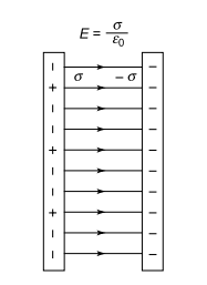
Field across charged parallel plates
Permittivity
In the equations describing electric and magnetic fields and their propagation, three constants are normally used. One is the speed of light C, and the other two are the electric permittivity of free space ε0 and the magnetic permeability of free space, μ0. The magnetic permeability of free space is taken to have the exact value
μ0=4π×10−7 N/A2
This contains the force unit N for newton and the unit A is the ampere, the unit of electric current. The magnetic permeability and the electric permittivity are related by the equation
C=1/√(μ0 ε0 ) where C is the speed of light, C = 2.99792458 *108 ≈ 3*108 m/s
This gives a value of permittivity of free space (or vacuum):
ε0= 8.854187817 *10–12 F/m
The vacuum permittivity μ0 (also called permittivity of free space) is the ratio D/E (D being the flux density of electric field) in free space. It also appears in the Coulomb force constant 1/4π ε0 where C0 is the speed of light in space, and μ0 is the permeability of vacuum.
These expressions contain the units F for Farad, the unit of capacitance, and C for Coulomb, the unit of electric charge. In the presence of polarizable or magnetic media, the effective constants will have different values. In the case of a polarizable medium, called a dielectric, the comparison is stated as a relative permittivity or a dielectric constant. (In the case of magnetic field, the relative permeability is specified.)
The examples above show that whatever the geometry of the charged body, it will carry an associated electric field. This statement can be extrapolated to say that an electrified wire, or any charged substance inside or near another body or equipment can affect it by its electric field, and will exert a capacitive effect. This has a very important bearing on various sensitive equipment and measurements.
In electromagnetism, permittivity is the measure of resistance encountered when forming an electric field in a medium. In other words, permittivity is a measure of how an electric field affects, and is affected by, a dielectric medium. Permittivity is determined by the ability of a material to polarize in response to the field, and thereby reduce the total electric field inside the material.
Thus, permittivity relates to a material’s ability to transmit (or “permit”) an electric field. It is directly related to electric susceptibility, which is a measure of how easily a dielectric polarizes in response to an electric field. In SI units, permittivity is measured in farads per meter(F/m); electric susceptibility X is dimensionless. Permittivity of a dielectric is
ε=εrε0
where εr is the relative permittivity of the material. The electric displacement field D represents how an electric field E influences the organization of electrical charges in a given medium, including charge migration and electric dipole reorientation. Its relation to permittivity in the very simple case of linear, homogeneous, isotropic materials with ‘instantaneous’ response to changes in electric field is
D=εE
where the permittivity is a scalar. In general, permittivity is not a constant, as it can vary with the position in the medium, the frequency of the field applied, humidity, temperature and other parameters. In a nonlinear medium, the permittivity can depend on the strength of the electric field. Permittivity as a function of frequency can take on real or complex values.
Materials with a large amount of loss inhibit the propagation of electromagnetic waves.
Dielectrics are associated with lossless or low-loss materials. A perfect dielectric is a material that has no conductivity, thus exhibiting only a displacement current. Therefore it stores and returns electrical energy as if it were an ideal capacitor.
The electric susceptibility Xe (Latin: susceptibilis ‘receptiveness’) of a dielectric material is a measure of how easily it polarizes in response to an electric field. This, in turn, determines the electric permittivity of the material and thus influences many other phenomena in that medium, from the capacitance of capacitors to the speed of light. Xe is defined as the constant of proportionality (which may be a tensor) relating an electric field E to the induced dielectric polarization density P such that
P= ε0XeE
where ε0 is the electric permittivity of free space. In general, a material cannot polarize
instantaneously in response to an applied field, and is time dependent. The susceptibility of a medium is related to its relative permittivity ε by
Xe=εr-1 (so vacuum has zero susceptibility)
Capacitance
A capacitor is a passive component that stores the electric charge. It is essentially a pair of conductors which contains movable electric charge separated by a dielectric (or insulator). A potential difference must be present to create a voltage between these conductors. As the energy is stored, a mechanical force is produced between the conductors. This is most common between flat and narrowly separated conductors.
The concept of capacitance was first conceived in 1861 by James Clerk Maxwell. He invented the concept of displacement current, as the rate of change within the electromagnetic field. Maxwell understood the concepts of flow of electricity through insulators. He also understood how electromotive force would produce a state of polarization.
An ideal capacitor has a constant capacitance C, defined as the ratio of charge ±Q on each conductor to the voltage V between them. It will not have any resistive or inductive properties, hence would not dissipate any power. A real world capacitor consumes a small amount of power whenever current flows through it, due to ohmic losses.
In addition, under continuous AC there are dielectric losses, which are minor at supply frequencies but can get significant at higher frequencies, depending on the type of capacitor.
Capacitance is a measure of the ability of a capacitor to store electric charge. Capacitance is also a measure of the amount of electrical energy stored (or separated) for a given electric potential. If a capacitor is charged to a voltage V, it holds a charge +Q at one plate and –Q on the other; 1 coulomb is a unit of charge equal to 6.28 *1018 electrons. A capacitor of 1 Farad will accept a charge of 1 coulomb to change its potential by 1 volt.
C = Q/V So 1 Farad = 1 Coulomb/ Volt
Sometimes charge build-up affects the capacitor mechanically, causing its capacitance to vary. In this case, capacitance is defined in terms of incremental changes:
C = dq/dv
A coulomb is 1 ampere second. If 51 mA current for 1 second causes the voltage to change by 1 volt, the capacitance will be 51 mF. It has base SI representation of s4.A2.m–2kg–1. This gives rise to following dimensional equalities:
F = A.s/V = J/V2= C/V = C2/J = C2/ N.m = s2C2/ m2.kg = s4A2/m2.kg = s/Ω
C represents electric charge in SI system of units. Farad was considered too big a unit for practical use, and much smaller fractions, microfarad (μF), nanofarad (nF), picofarad (pF), and even ppF have been in circulation all along. Over the past two decades, with the development of electrochemical capacitors, unit of Farad (F) has come into use, along with kilofarad (kF). The capacitance of a pair of plates is determined by the formula
C = ε0ε .A/d
Where C = capacitance (Farads), ε0 = permittivity of vacuum, 8.85 *10–12 F/m, A = area (m²) and d = dielectric thickness (m), and εr is called the relative permittivity of the dielectric material, and denotes energy stored in a material by an applied voltage, relative to that stored in vacuum for a given geometry. This is also denoted by k, called the dielectric constant of the material. The above formula then becomes
C = 8.85 *10–12 kA/d
So, for example, a pair of plates of 0.01 m² area, separated by 1 μm, and having an insulation with a dielectric constant of 3 (e.g. polyester), will have a capacitance of about 260 nF. These plates might typically be a metallized layer of 10 mm width, and having a length of 1 m.
If a number of capacitors are connected in series or parallel connections, as shown in Fig,
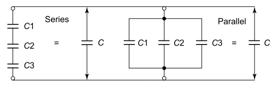
Series and parallel connection of capacitors
the resultant capacitance is given as follows:
Capacitors in series: 1/C=1/C1+1/C2+1/C3
Capacitors in parallel: C=C1+C2+C3
(It may be noted that these relations are exactly opposite to those applicable for resistors or inductors.)
Charging a capacitor
When a DC supply is connected to a series resistor and capacitor, the initial current is high as the supply source transports charge from one plate of the capacitor to the other. The charging current asymptotically approaches zero as the capacitor becomes charged up to the supply voltage (see Fig).
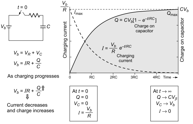
Charging process of capacitor
Charging the capacitor stores energy in the electric field between the capacitor plates. The rate of charging is typically described in terms of a time constant RC, R being the resistance connected in series with capacitor, inclusive of equivalent series resistance of capacitor (see Fig).
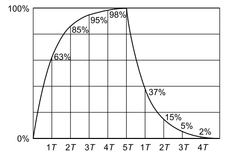
Charge-discharge cycle(T=RC=Time constant)
Note that the charging proceeds exponentially with time, and current goes on reducing,
from a maximum at time zero to almost zero after 5 time constants. The voltage followsa reverse curve, starting from zero and reaching near – full voltage at time 5T. A capacitor acts like a short circuit at the instant of applied voltage, and an open circuit when the full voltage is reached.
Table shows the progress of charge voltage on a capacitor in terms of multiples of time constant RC for the charging circuit.
Charging voltage variation with time constant
| Time | 0 | 1RC | 2RC | 3RC | 4RC | 5RC |
| Voltage | 0 | 63% | 86% | 95% | 98% | 99% |
Capacitors return their stored energy fully to the circuit. The energy stored by a capacitor is much smaller than that stored by a battery, so capacitors are not a practical source of energy for most purposes.
As opposite charges accumulate on the plates of a capacitor due to the separation of charge, a
voltage develops across the capacitor due to the electric field of these charges. Ever-increasing
work must be done against this increasing electric field as more charge is separated.
The energy (in joules) stored in a capacitor is equal to the amount of work required to establish the voltage across the capacitor. The energy stored is given by:
Stored Energy E = ½CV2= ½Q2/C = ½VQ
where V = voltage across the capacitor.
Current in a capacitor
The impedance of a capacitor can be calculated based on the current through it and the voltage across its terminals. A real capacitor is made from two conductors separated by a dielectric. Process of current flow from one conductor to the other, when it has an insulating dielectric
between them, is a fundamental question. Real current does not really flow through a capacitor, though it appears so when the voltage across the capacitor changes.
If the voltage across the capacitor in Fig were to increase, some positive charge would have to be added to the top conductor and some negative charge would have to be added to the bottom conductor.
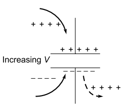
Increasing voltage across a capacitor
Adding negative charge to the bottom conductor is the same as pushing positive charge out; it is as though positive charges were added to the top terminal and positive charges were pushed out of the bottom terminal.
Assuming that the width of the plates is much greater than their separation d, the electric field near the centre of the device will be uniform with the magnitude E=ρ/ε . The voltage is defined as the line integral of the electric field between the plates.
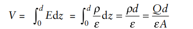
Solving this for C = Q/V reveals that capacitance increases with area and decreases with
separation
C=ε A/d
The capacitance is therefore greatest in devices made from materials with a high permittivity. A capacitor opposes a change in voltage, and its current depends on rate of change of voltage.
I = CdV/dt
Current I is in amperes, voltage V in volts and time t is in seconds. This relationship reaffirms that the only way current flows through a capacitor is when the voltage across it changes. If the voltage is constant, the current through a capacitor is zero. The current through it doubles only if the rate of change of the voltage across it doubles.
No current flows in a capacitor once a steady state DC voltage is established across it. However, a current will flow with every change of voltage, or under surge conditions. If a steady AC voltage of an ideal sinusoidal waveform is applied, it can be derived that the current through a capacitor is
I=2πfCV,I=ωCV
where ω = 2πf is the rotational angular frequency of applied voltage. The current in a capacitor is directly proportional to the frequency of applied voltage.
The real capacitor can be modelled as an ideal capacitor in series with an ideal inductor and an ideal resistor in series. The ideal inductor represents the capacitor’s Equivalent Series Inductance (ESL) and the ideal resistor, the capacitor’s Equivalent Series Resistance (ESR).
The ideal capacitor impedance is infinite at DC and decreases as the applied voltage increases in frequency. Eventually, the ideal capacitor’s impedance reaches zero. The real capacitor’s impedance never reaches zero because of ESR and ESL.
Non-ideal behaviour
Real life capacitors deviate from the ideal capacitor in a number of ways. Some of these deviations,like leakage current and parasitic effects are linear or near linear, and can be dealt with by adding resistive and inductive components in the equivalent circuit of the capacitor.
In other cases, such as with breakdown voltage, the effect is nonlinear and normal linear network analysis cannot be used. There is yet another group, where capacitance may be linearly related to some other variable like temperature or pressure.
[The symbol j = √−1 is used in electrical engineering to denote the vectorial reactance component of impedance, 90º out of phase with the resistive (active) component. +j indicates inductive, while –j indicates capacitive reactance.]
XC=V/I=1/ωC is called reactance of a capacitor is called reactance of a capacitor. Capacitive reactance (Xc) is a measure of an ideal capacitor’s opposition to AC (alternating current). Like resistance, it is measured in ohms, but reactance is more complex because its value depends on the frequency (f) of the electrical signal passing through the capacitor as well as on the capacitance, C.
VAR=I*V=2πfCV2
The resistive component of capacitor is too small, so the above formula holds true almost all the time. It follows that a capacitor acts as an open circuit for DC voltage, and a short circuit path for very high frequencies. If its equivalent series resistance is R then the watt loss in capacitor becomes W = L2R.
ESR and Q
A capacitor’s quality factor (Q) is numerically equal to the ratio of its net reactance (XC– XL) to its equivalent series resistance. It can be seen that the capacitor’s Q varies inversely to its ESR and directly with the net reactance
Q = (Xc – XL)/ESR
Equivalent Series Resistance (ESR) is the summation of all losses resulting from the dielectric and metal elements of a capacitor and is typically expressed as milliohms. ESR is a key parameter to consider when utilizing capacitors in RF bypass applications. In electronic circuits, a capacitor’s ESR should be known at all frequencies within the passband, especially at frequencies above the capacitor’s series resonant frequency.
The ESR will increase for increasing frequencies and may become the dominant loss factor. It will largely determine the attenuation at the parallel resonant frequency.
Impedance: (Z) The magnitude of a capacitor’s impedance, accounting for ESR and ESL, is equal to:
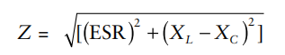
If inductance ESL is negligible, absolute value of
(Usually ESR << Xc, and Zc is the reactance of ideal capacitor.) Zc is a vector quantity, and j shows vector quantity at right angles to the resistive component R. The minus sign is for leading power factor.
Hence I = ωCV (presuming R << Xc)
The apparent power drawn by capacitor, called reactive power, is calculated as Zc = R – j(1/ ωC), where R is the equivalent series resistance of a capacitor. Usually, R is too small and negligible, and the above equation reduces to
Zc = Vc/Ic = – jXc = –j(1/ ωC)
DC current in capacitors
The dielectric between the plates is an insulator and blocks the flow of electrons. A steady current through a capacitor deposits electrons on one plate and removes the same quantity of electrons from the other plate. This process is commonly called ‘charging’ the capacitor. The current I through the capacitor is the rate at which charge Q is forced through the capacitor (dQ/dt). This can be expressed mathematically as:
I = dQ/dt = CdV/dt
For circuits with a constant DC voltage source, and consisting of only resistors and capacitors, the voltage across the capacitor cannot exceed the voltage of the source. Equilibrium is reached where the voltage across the capacitor is constant and the current through the capacitor is zero. For this reason, it is commonly said that capacitors block DC.
AC current in capacitors
The current through a capacitor due to an AC source reverses direction every half cycle. Except for the instant that the current changes direction, the capacitor current is non-zero at all times during a cycle. For this reason, it is commonly said that capacitors ‘pass’ AC.
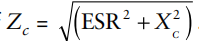
The voltage across a capacitor is proportional to the integral of the current, with sine waves in AC or signal circuits. This results in a phase difference of 90°, the current leading the voltage phase angle, as shown in Fig. The amplitude of the voltage (v) depends on the amplitude of the current (I) divided by the product of the frequency (f) of the current with the capacitances, C.
Current and voltage waveforms for a capacitor
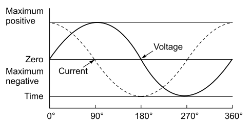
Equivalent circuit of capacitor
The generalized equivalent circuit of a capacitor is shown in Fig. The nominal capacitance is the value of C, with ESR and ESL (equivalent series resistance and inductance) in series. The parasitic capacitances (C2 – Cn) and their series resistances represent the dielectric loss (resistance) and dielectric absorption.
Lumped equivalent circuit of 1 μF capacitor
These are infinite, with ever diminishing capacitance and increasing series resistance. The values used are for simulation purposes. It must be understood that dielectric loss, residual charge, series resistance and inductance are quite normal, and appear in all components.
If a meter is connected between the capacitor terminal and its metal case (or a metal foil around the outer surface), it measures a capacitance value, although small. This is because the case serves as one capacitor electrode while the main capacitor element is the second electrode.
Dielectrics
A dielectric is an electrical insulator that can be polarized by an applied electric field. In an electric field, electric charges do not flow through the dielectric material, as in a conductor, but shift only slightly from their average equilibrium positions (dielectric polarization).
Positive charges are displaced toward the field and negative charges in the opposite direction. This creates an internal electric field which reduces the overall field within the dielectric itself. If a dielectric is composed of weakly bonded molecules, those molecules further reorient to align with the field.
Although ‘insulator’ implies low electrical conduction, the term ‘dielectric’ is used to describe materials with a high polarizability, which is expressed by a number called the dielectric constant. A common example of a dielectric is the electrically insulating material between the metallic plates of a capacitor.
The study of dielectrics is concerned with the storage and dissipation of electric and magnetic energy in materials. The term ‘dielectric’ was coined by William Whewell in response to a request from Michael Faraday.
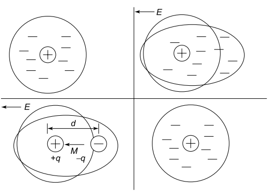
Atomic model of a dipole
A dielectric material is made up of atoms. Each atom effectively consists of a cloud of negative charge (electrons) bound to and surrounding a positive point charge at its centre. An electric field distorts the cloud as in Fig. The cloud thus displaced can be represented by a dipole and its dipole moment M, a vector quantity.
Like flowers that bloom in unexpected places, every story unfolds with beauty and resilience
The relationship between the electric field and the dipole moment gives rise to the behaviour of the dielectric. (Note that the dipole moment is shown to be pointing in the same direction as the electric field, which is mostly the case.) When the electric field is removed the atom returns to its original state. The time required to do so is the so-called relaxation time, an exponential decay.
Dielectrics materials
The dielectric of a capacitor and its thickness is determined by factors such as the type of capacitor, its voltage rating, application, operating temperatures, duty cycle and life expectancy. An important property of a dielectric is its ability to support an electrostatic field while dissipating minimal energy in the form of heat. The lower the dielectric loss (the proportion of energy lost as heat), the more effective is a dielectric material.
Another consideration is the dielectric constant, the extent to which a substance concentrates the electrostatic flux. Substances with low dielectric constant include a perfect vacuum, dry air and most pure, dry gases such as helium and nitrogen.Materials with moderate dielectric constants include ceramics, distilled water, paper, mica,polyethylene and glass. Metal oxides, in general, and some ceramics have high dielectric constants.
The prime asset of high-dielectric-constant substances is the fact that they make possible the manufacture of high-value capacitors with small physical volume. But these materials generally do not withstand electrostatic fields as intense as low-dielectric-constant substances such as air.
(a) Permittivity and Dielectric Constant
Permittivity (ε) may be visualized as space factor, or an indicator of capacitance packing in a given space. It is known that most dielectrics have permittivity higher than vacuum. The higher the permittivity, the smaller is the space requirement for a given capacitance value. It is customary to mention these values in comparison with this reference, and as a multiplier of permittivity of vacuum ( ε0).
This is called relative permittivity, or Dielectric Constant, and is represented by letter r or k, which appears in the capacitance formula. Values for k differ widely, from 1 (vacuum) to several hundred or a few thousands. While permittivity is relatively constant, it tends to vary with temperature, and sometimes with frequency.
(b) Dielectric Strength
Voltage applied on a capacitor may be increased gradually, and its energy stored will go up in squared ratio to voltage. If the voltage across a dielectric material becomes too great – that is, if the electrostatic field becomes too intense – the material will suddenly begin to conduct current. This phenomenon is called dielectric breakdown. In components that use gases or liquids as the dielectric medium, this condition reverses itself if the voltage decreases below a critical point.
But in components containing solid dielectrics, dielectric breakdown usually results in permanent damage. The operating voltage stress of capacitor dielectric is kept much below this limit. The life of a capacitor is much longer and operational safety higher at safer voltage levels. Various dielectrics have different breakdown strengths, and have to be considered for this property for a given application.
Dielectric strength is dependent on temperature, frequency, shape of electrodes or clear
insulating margins towards winding ends. The strength of base material like kraft paper may be substantially increased by use of impregnants.
The working voltage stress on a capacitor dielectric is among the highest compared to most insulation materials used anywhere. A modern metallized capacitor for a motor may use a working stress in excess of 60 KV AC per mm.
(The dielectric will have breakdown strength of over 400 KV DC per mm. By comparison, vacuum or dry air has breakdown strength of 3 KV DC per mm.) Even higher stresses may be used in future capacitors.
In high current applications, there will be significant voltage across the capacitors. They must withstand the voltage and current that they will be subjected to. This is an area where dielectric loss may cause the capacitors to heat up with sustained high power, and the devices used need to be stable with time and temperature.
The size of capacitors varies widely from miniscule (the size of sand granules) to large ones requiring special enclosures or rooms. They come in cylindrical shape, disc type, in boxes, with or without mounting studs or brackets. Case materials may be steel, aluminium, or a variety of plastics.
Terminations can be of wires, solder tags, and slip type terminals, screws and bolts, with or without special bushings. They may also be Surface Mounting (SMD) type, which are soldered directly to PCBs in electronic circuits, without any wire leads.
Capacitors may be used anywhere from – 40°C to +100°C or even higher temperatures,and may be used on mountaintops or under the sea. Space ships also use them under extreme conditions of reliability in zero gravity. From highly salty conditions on seashores to deserts, a capacitor has to be found for any weather.
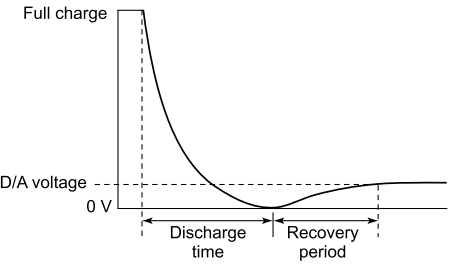
Dielectric absorption
This is the phenomenon that allows a capacitor to recover some of its original charge due to dielectric absorption. If a capacitor is charged fully and then discharged, the voltage is seen to rise again, as shown in Fig, even though it was obviously zero for the duration of the short.
Dielectric absorption phenomenon
The dipole orientation of capacitor dielectric materials reverts to its natural neutral position when its external voltage is removed, and the capacitor is discharged. However, all dipole energy is not discharged instantly (due to inertia), but the dipoles get reoriented after removal of external discharge path.
Since dipoles do not lose their energy fully, when the external discharge path is removed within a short time, a process of dipole reorientation begins by virtue of their residual inertial energy, resulting in a small voltage appearing across the capacitor terminals.
However, if capacitor terminals are shorted for a sufficiently long time, the dipoles get enough time to lose all their energy and fall back to their natural positions, and the voltage does not reappear.
This inertia is quite large in electrolytic and electrochemical capacitors: so large that these capacitors have to be kept shorted for a long time to neutralize their charge fully. In fact, electrochemical capacitors take anywhere from fifteen minutes to a few hours to reach stable voltage zero, i.e. to have no adsorption effect apparent.
General construction of a capacitor
Figure shows the general construction of a multilayer capacitor, and is also representative of the cross-section of a traditional extended foil capacitor. With some capacitors, one end is marked with a band or is otherwise indicated as the outer foil.
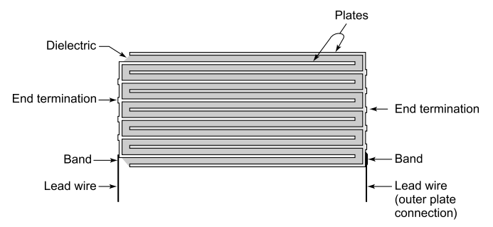
Multilayer capacitor construction,or cross-section of extended electrode wound element
This can be useful for sensitive circuits, where the outer foil (or plate) ends may be connected to earth (ground/chassis) to shield the capacitor against interference. This is usually only needed in very high impedance circuits, or where there is considerable external noise.
The way the ends of the foil are joined in these capacitors prevents the signal from having to traverse the length of the plates. This is referred to as ‘non-inductive capacitor’, as practically all turns or layers have been shorted, and only the inductance of terminal wires and the width between ends are significant for inductance.
General notes on soldering of capacitor leads:
Permissible heat exposure loads on capacitors are determined by the upper category temperature Tmax. Long exposure to temperatures above this type-related temperature limit can lead to changes in the plastic dielectric and thus change a capacitor’s electrical characteristics irreversibly. High temperatures are encountered during soldering, but these are only applied briefly and not allowed to affect the plastic base.
Apart from being dependent on the solder bath temperature and the soldering time,
the thermal load is also affected by the initial (pre-heating) and the post-soldering (cooling) temperatures.
Shadowing by neighbouring components or subsequent heating due to their effect has a similar result. Since the soldering heat is transmitted into the components mainly via the leads, the thermal resistance of the terminals is the deciding factor for the heat transmitted, especially for smaller capacitor sizes.
Thus a poor thermal conductivity is desirable from this aspect, however, this is contrary to good electrical conductivity required in order to achieve low dissipation factors, since the electrical conductivity is generally proportional to the thermal conductivity.
Codes for values of electrolytic capacitor
Electronic capacitors which are small in size carry their values, tolerances and voltages in the form of colour codes or digital codes. Table below gives the standard colour codes in use for capacitors.
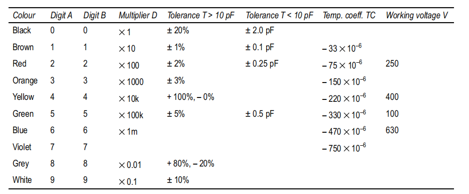
Colour Codes for Electronic Capacitors
Capacitor characteristics
Each type of capacitor is distinguished by its own unique characteristics. Even within a given type,
the choice will depend upon the specific dielectric selected for desired end use. As temperatures
change, capacitance values also change. This is termed as the temperature coefficient of
capacitance (TCC).
For ceramic capacitors, the voltage applied to the capacitor also affects the capacitance value (the electric field strength across the dielectric changes the effective dielectric constant K of the material). The capacitor cost and size need to be considered, as well as its packaging type.
End-of-life reliability issues may also be important. Each capacitor type has its own set of
characteristics that will make it the most logical choice for a given application.
Capacitor – physical sizes
- Smallest discreet capacitors can be just the size of sugar granules.
- Large Power Factor Capacitor banks need more space to house them.
- SMD capacitors are among the smallest variety.
- Integrated circuits have capacitors etched in semiconductor circuits.
Capacitor performance requirements
- Long working life.
- Wide range of working temperature, (typically – 25ºC to +85°C).
- No damages to surroundings in case of failure.
- High stability of the capacitance value during the working life, in particular for series connected KVAR capacitors.
- The life of a capacitor depends mainly on its working conditions. Temperature and voltage are particularly important in this respect.
- It may be noted that each 10°C rise of the working temperature causes a 50% reduction of the capacitor life. Usually the following formula is adopted:
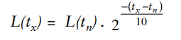
Where L(tx) is the capacitor life at temperature tx;
L(tn) is the capacitor life at the maximum rated temperature.
Applications in industry
Table below outlines typical functions performed by capacitors in electrical and electronics circuits:
| Function | Representative application |
| Energy storage | Photoflash,Timers,Vehicles |
| Resonant circuits | Oscillators, Tuning |
| Smoothing | Power Supplies |
| H.F.filters | DC Supplies, R.F. Suppression |
| Phase shifting | Motors, Fans |
| Measurement and sensors | Vacuum, electrical and mechanical parameters |
| Capacitive switching | Touch Control |
| Transient suppression | Power Supplies |
| Peak voltage generation | Auto Industry |
| Commutation | Traction, series motors |
| Isolators and couplers | DC electronic circuits |
| Motor starting and running | AC capacitor run/capacitor start |
This is only representative and capacitors find place in wide range of applications in the electrical and electronics industry. Practically every electronic circuit and most electrical systems use capacitors in some form, performing a variety of functions. Radios, TVs, cars, planes, mobile phones, washing machines, pumps, motors, and generation and distribution systems, traction, commutation…the list is endless.
Electrolytic capacitors are excellent for power supply, and in most places where high values of capacitance are needed. They are unsuitable for filters, because they have wide tolerance, should be biased, and may change capacitance depending on applied frequency. Bipolar electrolytics are excellent where high values are needed, and no polarizing voltage is available. Because of wide tolerance, they too are unsuitable for filter circuits.