Metallized films in capacitors
Use of metallized films has virtually taken over most capacitor applications in the past few decades. The advantages offered by metallized films have proved to be of immense value in major areas by way of low mean time between failures (MTBF) and long life.
They are able to take on much more stress compared to conventional paper/foil or film/foil designs, and have helped reduce capacitor sizes considerably.
Metallized polypropylene (MPP) film used for AC capacitors is very thin in nature, of the order of 4 to 10 microns in thickness. Typically, an 8-micron thin film used for a 440 V AC capacitor bears a working voltage stress of 55 V per micron (i.e. 55 kV/mm).
The peak voltage stress for this sinusoidal voltage is 55* √2 = 77 kV/mm. Voltage stress during a 1-minute HV test is 1.5 to 2.15 times this value. With 7-micron film, working stress will go up to 63 V/μ AC and test voltages about 125 V/μ AC.
To imagine the magnitude of this voltage, consider that a normal PVC wire used in AC mains has a typical insulation thickness of 0.5 mm for 250 V AC rating, which works out to 500 V/mm (0.5 kV/mm AC). Further, breakdown voltage of dust-free dry air (or vacuum) is 3 kV/mm (DC). These are insignificant values compared to stresses of capacitor dielectrics.
The dielectric film has to be of very high purity to work under such stresses, and also be practically free of weak spots and pinholes etc. With improvement in materials and manufacturing techniques, including development of sophisticated machinery, AC working voltage stresses have increased from 40 to 42 V per micron to 60 to 65 V per micron over two decades, and stresses of higher magnitudes are being used in modern capacitors.
The thin film, and its high working stress, demand that the materials used in capacitors retain their purity during manufacture and use. Dust particles in normal air, of the order of 4 to 10 microns, are invisible to the naked eye.
Any particles entering the dielectric of comparable thickness get embedded in the layers, and create weak or conducting points. Hence the winding room has to be absolutely dust-free and other working areas must also be meticulously maintained.
The PP film is quite susceptible to changes in temperatures, and a change in temperature during storage or use can cause warping and creases. A working temperature of 25 – 27°C and a relative humidity not exceeding 55% to 65% is generally recommended for film storage and the working environment.
These conditions are maintained at the time of manufacture and processing of films, and have to be observed at the time of their use in capacitor manufacturing process for best results.
Metallized electrode
The metallized electrode coating was first developed using vacuum deposited aluminium. Though aluminium has high stability in normal storage conditions, demand for greater capacitance stability in AC applications led to the development of zinc coating.
Zinc gives much more stable capacitance value over time, but has very low storage life and is also highly susceptible to heat, air and moisture. Hence, zinc aluminium alloy metallization was developed, and is now generally used.
The thickness of the metal deposit has to be accurately controlled. If it fails to evaporate and isolate a defective spot, a permanent short circuit will form and the capacitor will go out of service.
Aluminium is hard to beat for cost and reliability. Hence it is still the preferred choice for DC capacitors. Zinc has been used for its better healing properties, but it is more vulnerable to corrosion. Zn-Al alloys are now used in large, high-voltage film capacitors for more reliable self-healing.
A layer of aluminium is first coated, and immediately thereafter, a zinc coating is made on the film. Aluminium partially comes to the surface during process, and improves storage capability (shelf life) of the film. These films have better storage stability compared to those with plain zinc metallization.
The coating of the metal electrode layer is extremely thin, just around 0.02–0.03 μm, and it cannot be measured by normal mechanical methods. Hence, an indirect method of measuring the resistivity of the electrode surface is used.
Resistivity is measured in ohms per unit area, and is given as ‘ohms per square’ or ‘ohms sq–1’ (Ω –1). This is because the resistivity measured over any perfectly square area is the same, irrespective of the unit of length. This can be easily verified mathematically.
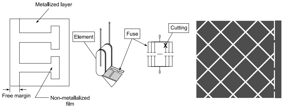
The metallized film has a metal-free edge clearance at one end – usually 2 to 2.5 mm for 440 V capacitors. In every capacitor, the two layers of film will have free margins at opposite edges, and metallizing on the films is on the opposite edges.
Round coils are wound and the edges are sprayed with zinc. A conducting lead is soldered onto these surfaces. There is a microscopic layer of air between these layers. The coils are wound tight. They are further shrunk under heat treatment. This reduces the air thickness between layers very significantly.
The non-metallized free margin plays a significant role in deciding the safety factor and as insulation between two metallized electrodes. The higher the capacitor voltage, bigger is the margin.
The smallest margins used today can be as low as 0.5 mm in some very low voltage DC capacitors, while 2–2.5 mm is common for 250–440 V AC power applications. Power capacitors may see margins going up to 5 mm, while electronic capacitors may use 1–1.5 mm margins.
Efforts to improve the quality and performance of films led to the development of trilayer metallization. In this process, an extremely thin silver deposition is made on film before metallizing with zinc and aluminium.
Silver has better adherence to base film, and this gives a distinct advantage over the normal zinc alloy films by way of better stability. Using silver in addition to aluminium and zinc, the three-layer metallization overcomes the shortcomings of conventional types of metallization and improves capacitance stability and shelf life of zinc alloy metallized film.
The function of silver is to improve adhesion of zinc to the base film. Three-layer zinc-alloy metallization with reinforced edge facilitates superior end spray adhesion, thereby improving the surge withstanding capability of sprayed elements.
Al and Zn metallized film, multilayer metallized film with coating of Al, Ag and Zn-Al solves the problem of rapid oxidization of Zn while maintaining all the merits of Zn.
Self-healing
The process by which the electrical properties of a metallized capacitor are restored rapidly after a local breakdown (including partial discharge), to the values before breakdown, is termed self-healing. Self-healing is absolutely critical for long-term reliability for high-energy film capacitors.
Since all the defects in a single layer of MPP can be healed during the manufacturing process, a single-layer capacitor can be formed quite comfortably with higher operating dielectric voltage stress.
In the event of a weak spot on the film appearing during manufacture or subsequently in service, the resultant energy discharge through the weak spot vaporizes the surrounding coating.The weak spot gets isolated, as shown in Fig, and the capacitor continues to remain in service, practically intact.
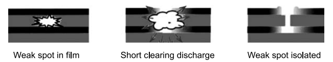
Self-healing process
These capacitors are hence called ‘self-healing capacitors’. (The area around the weak spot so cleared is de-metallized, and the active area of the capacitor gets reduced with every self-healing operation, causing a small drop in capacitance value.)
If the fault is cleared without sufficient energy, or a series of clearings occurring successively, the area around the cleared spots has lower insulation resistance due to incomplete vaporization of metal, and becomes a leakage current path. Every such clearing adds to the loss factor, and in the long run, may develop thermal runaway, damaging the unit completely, or even causing a fire.
Plain and heavy edge metallization
Normally for all DC applications and some AC applications, metallization is uniform (plain) over the film surface, and the metal used is aluminium, being cheapest and very stable, with excellent storage life.
However, with the advent of zinc for metallization, a search for better self-healing properties led to the development of heavy edge film, where the edges are made thick to enable good contact with sprayed metal and also to have better current density at current collecting areas, and metallization thickness on active area is reduced considerably.
The evaporation of surface metal is much more efficient because of thinner coating, while heavier zinc or Zn-Al coating at the edge makes for normal and reliable end contact with sprayed zinc metal. Only aluminium metallization is normally used for BOPP or polyester film in DC applications for easy handling of capacitors manufactured with oil impregnation.
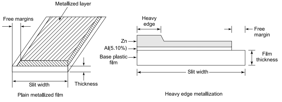
Plain and heavy metallized films
Surface resistivity of metallized films
For plain metallization 2 to 4 Ω–1 is usual, whereas for heavy edge films, 2 to 4Ω –1 on edges and 6 to 10Ω–1 on main (active) area, are found to be generally acceptable. These are found to give optimum performance for AC capacitor applications. The average resistivity measured over the entire width of film is between 5 and 9Ω –1.
These parameters can change on the lower side (thicker coating) 1 to 2Ω –1 and 2 to 4Ω –1 respectively for special application capacitors subjected to heavy current surges (commutation and auto ignition, for example).
Heavy edge resistivity is usually half to one-third of active area resistivity. Usual metal free margins lie between 1 and 2.5 mm, and heavy edge widths of 2 to 3 mm are common.
The resistivity, apart from giving a measure of proper coating thickness, also gives an idea of the purity of metallization, since any oxidation of metal surface by atmospheric effect or moisture causes an increase in resistivity.
The resistivity of active area, heavy edge area and the average resistivity need to be measured separately at manufacturer’s end, and instruments are specially designed for this purpose. For certain critical applications like auto ignition or commutation capacitors, the resistivity needs to be much lower, almost half of the above figures (i.e. heavy metal coating) to take care of heavy current densities or discharge currents.
The metallized layer is very sensitive to handling and if rubbed, the metal can be simply erased out of the film. Hence any physical contact with the metallized end of film roll or the wound element must be avoided.
The film should be held from its winding core (plastic or metal cylinder) while handling or loading on machines. Further, it should not be exposed to any dust or moisture in storage/handling. The film also develops creasing or warping at higher temperatures, and it should be preferably acclimatized at winding temperature for a few hours before use to get best results.
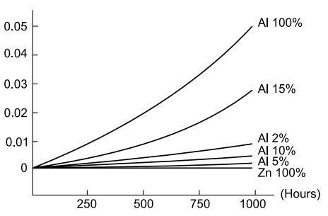
The stability of metallization can be judged by following the change in resistivity over time, and in zinc alloy metallization, is a function of aluminium content in the alloy.
As shown in Fig, an increase in aluminium content in metallization increases the stability, and hence the shelf life, of the metallized film. Film with pure Al metallization is the most stable, while pure zinc shows a very sharp deterioration in storage conditions.
The capacitance stability over the lifetime of a capacitor is far superior with zinc metallization, with practically no change over 1000 hours, and as the percentage of aluminium in metallization increases, the drop in capacitance goes up, as seen from Fig. An Al percentage of 2% to 10% keeps the drop within 1%, while beyond this, the drop increases sharply.
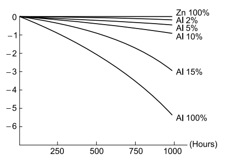
Capacitance stability for different proportion of aluminium C.
Similarly, the loss factor of a capacitor undergoes no change for a pure zinc metallization, and as the percentage of aluminium in metallization goes up, the loss factor stability gets worse, as seen in Fig.
Tan delta stability over time as aluminium Contents C.
Here also, the increase in tan delta remains within fair limits for aluminium content up to 10%. It is thus seen that from the point of view of both capacitance stability and tan delta deterioration, Al percentage must be below 10%. Actual results may vary depending upon manufacturer and process refinement.
Zinc alloy with varying composition gives different results, and further there is some variation in different manufacturers’ products depending upon the process. Today films are available with sloped metallization, where the metallization thickness decreases with the distance from heavy metallized edge.
The current density on the film decreases away from the heavy edge, and the self-healing can take place at lower current densities at weak spots. This improves the failure recovery mechanism of the capacitor.
Comparison of metallization compositions
A comparative behaviour of different types of metallization is given in Table below.
Table Comparison of Zn, Zn-Al Alloy and Al Metallized Films
| Shelf life | Self-healing property | Capacitance stability | Atmospheric stability | |
| Zinc | Poorest | Best | Best | Poorest |
| Zinc/Al | Moderate | Better | Better | Poor |
| Aluminium | Best | Poorer | Lower | Best |
Film resistivity standards as followed for different metallization types are shown in Table. This is standard practice and developed after experimentation and study of field results.
Table Resistivity Standards for Zn/Zn Alloy and Al Metallization
| Standard resistivity | ||
| Film type | Active area | Heavy edge |
| Zinc /alloy | 7.5±1.5Ω-1 | 3.0±1.0Ω-1 |
| Aluminium | 1-2Ω-1 | 2-4Ω-1 |
Resistivity values much lower than above indicate heavier thickness, resulting in difficulty in proper short clearing. Higher values are the result of insufficient metallization, and the capacitor will not be able to carry the current safely.
However, in sloped metallization, metallization thickness is heaviest near the heavy edge contact side, and goes on reducing towards the non-metallized free margin. This is because the current from the entire width of film is collected at the heavy edge, and current densities are consequently lesser as we move away from the current collecting heavy edge.
The logic in sloped metallization is to make short clearing easier at any spot by relating it to the current density at that spot.
Segmented films
One method to improve self-healing is to ‘segment’ the metallization. Instead of metallizing all of the film, the metallization is laid down in many rectangular or diamond-shaped patches which are connected by narrow metallized ‘bridges’.
Patterned film, or segmented film has been developed, where the metallization is not continuous, but a series of rectangular or crossed sections of metallized sections, which are joined to each other by small restricted paths.
These paths act as fuses, and in the event of a weak spot appearing in a section, the self-healing takes place in these pathways and the entire section is isolated. This eliminates the possibility of low resistivity paths being developed, and the capacitor retains good dielectric properties.
The segmented design also ensures that in the event of failure at a point on the dielectric, the corresponding area is isolated and the capacitor continues working normally, reducing the chances of low resistivity paths and consequent thermal runaway.
Several designs of segments are available for various capacitor applications, depending on film size and reliability desired. Segmented film capacitors have a conventional winding structure with unique segmented metallized electrodes.
These electrodes form a parallel connection of many small value capacitors. Should dielectric breakdown occur due to over-voltage, only the faulty small segment is disconnected resulting in an open circuit, thereby preventing the entire capacitor from burning.
The segmentation pattern in the metallized electrode allows localized fusing and disconnects during high voltage surges. However, self-healing by this mechanism can result in a progressive loss of capacitance, a potential problem in some applications.
Hence a potential downside is limited useful lifespan due to capacitance drop should excessive clearings and defusing occur.
Capacitor technology in the higher volume power applications starts at the higher input voltages. The pressure to downsize the input EMI filters has caused a redesign of many capacitors from PET film to segmented PP film.
Segmentation of the metallized patterns on thinner polypropylene has allowed higher values and a slight decrease in the package size of the ‘X’ capacitors. The trend toward higher voltage ratings per micron thickness has led to increased capacitance density.
The segmented film design has some drawbacks compared with regular metallized film:
- Loss of active area, e.g. diamond pattern consumes 10% more material Tan increases depending on the chosen resistance and pattern.
- Self-healing tests of several standards do not detect the fuses going off and this is misinterpreted as if no self-healing took place.
- The de-metallizing equipment in the winding machines may not always be compatible with segmented film.
- The winding quality of films thinner than 2 microns may be reduced compared to standard metallized films.
Segmented metallized films
Wave-cut films
When a zinc layer is sprayed on the ends of winding, it makes contact with the metallized edge of film. The edge is not in continuous contact with it, but since the spray is in granular form, the contact takes place at a series of points along the length.
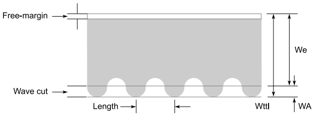
The collection of current is also accordingly through these points, creating points of concentrated current densities. Films have now been developed to offer better end contact with the sprayed metal layer. This is done by cutting the film edge in a wavy shape instead of straight.
This creates hills and valleys on the surface, and sprayed metal enters the spaces thus created. Figure shows the wave shape edges of these films. The spray thus holds the metal even from the sides, creating a much stronger bond. This adds to the stability of the metallized layer in service.
Wave-cut metallized films
This reduces the current density, and associated thermal stress, thereby increasing the current capacity of end surface for the same area. Reliability of the capacitor goes up by way of reduced failures on this count.
The wave cut distributes film tension layers more evenly, and causes less mechanical stress in pressing and heat treatment during capacitor manufacture. Since the current density is reduced, it may be possible to reduce film thickness for some capacitors.
However, very large winding offsets do not derive any benefit from wave cutting over straight cut films. Too small offsets reduce the contact area, and the wave may even stick out of the winding. The offset has to be equal to the wave amplitude to derive full benefit of better ESR, dv/dt and mechanical strength.
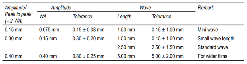
Table gives a general description and practical wave-cut film dimensions.
Table Description of Wave-Cut Film (Source : Steiner, GmbH)
Wave-cut metallized film was developed to enlarge the effective end surface area in order to improve the adhesive strength during the metal spray process. This in turn is effective for the improvement of the capacitor durability. Wave-cut metallized film is generally used for X2 type capacitors.
Series metallized (multisection metallized) flims
To get higher working voltages using metallized films, the metallization is done in sections, with clear margins between sections on one film.
In the second film, clear margins appear at the centres of metallized sections of the first film, with metallized ends appearing on both edges. A winding made with this film is in effect a series combination of multiple capacitors to give a high corresponding voltage.
This gives the benefit of ease of construction of capacitors, and since only the extreme ends are metallized, more reliable connections and reduced interconnections between capacitor sections give an added advantage. The capacitor is thus more reliable with better life expectancy.
In power capacitors, double dielectric capacitors are becoming common, and this type of film could be a preferred choice for obvious reasons. A series connected 2-section capacitor using this film appears as shown in Fig. It is possible to have multiple series sections for higher operating voltages.
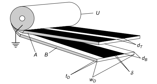
Series metallized flims
Typical Specification for a series metallized film could be :
Dielectric film thickness tD – 6 μm
Dielectric width WD – 55 mm
Metallization thickness dB – 20 nm
Axial track distance dT – 5 mm
Storage of metallized films
The nature of metallization and its susceptibility (particularly that of zinc) makes it necessary to store the metallized films in sealed condition until needed. They should also not be exposed to heat during storage.
The winding process has to be carried out in an air-conditioned and dust-free atmosphere, preferably under controlled humidity. The ideal conditions would be temperature of 23 to 27°C, and a relative humidity not exceeding 65%.
Further, once elements are wound, care has to be taken to avoid effects of surrounding atmosphere and moisture. It is further preferable that a pair of reels once unpacked should be used up on the same day.
MLP capacitors
Multilayer film capacitors evolved from stacked film types to the true surface mount chip styles are available today. Polymer dielectrics having no voltage or current dependency are the most stable system at higher voltages (including 24 and 48 V). Ultra-thin films in the 1.4-micron range for 100 V applications have led to highly stable film chips in large capacitance values.
High frequency ESR and ESL is comparable to the ceramic chips in X7R dielectric while the electrical stability is superior. Further reduction in size may happen by developing even thinner films and through the use of barrier coatings on these ultra-thin plastic films. Reduction in unit cost is also getting further attention.
Limitations of MPP films
Moisture getting in between layers oxidizes the thin metal deposits in its thickness fully. An oxidized boundary isolates a healthy section of a deposit, resulting in rapid or continuous fall of capacitor value.
This happens mainly in loosely wound capacitors or poorly made elements. The winding ends are normally sealed with resin or the coils are impregnated with an insulating liquid to prevent this.
1、Aluminium at the sprayed end forms a non-perfect joint with zinc spray – it corrodes more in the presence of moisture. This cuts off the entire healthy metallization below from the conducting edge, resulting in rapid fall of capacitance.
Heavy edge metallization helps prevents this. Zinc deposit over aluminium (Zinc alloy metallization) on the entire film surface also prevents this to a great extent. Nevertheless, care has to be taken to avoid or minimize exposure of metallized elements to moisture or oxidizing atmosphere.
2、Consider a large air void between layers and an irregularity in the form of a sharp point. As the voltage increases across the dielectric, electron streams originate from this sharp point and cut through the air path.
This is the beginning of a partial discharge. It creates hot spots and eventually causes failure of the element.
3、The most critical portion of the metallized capacitor is the edge gap. The full applied voltage appears across this gap between metallization at the end of margin of one film to the sprayed end of the other.
It is spread on a very thin metallization base 0.2 to 0.3 microns thick as against 5 to 6 microns thick foil in extended foil traditional capacitors. The voltage stress is very high – leading to instant or even sustained partial discharges, should the voltages cross the air gap strength.
Normally a 2.5 mm gap across a 0.3 micron base can sustain AC voltages up to 440 V + 10%. This makes these capacitors unsuitable where there are steady high voltages or sudden and continuous voltage fluctuations.
Metallized VS. non-metallized capacitors
[A] Advantages of metallized film capacitors
- The metallized coating on films is extremely thin, of the order of 0.02 to 0.03 microns. Hence a large reduction in capacitor volume is achieved compared with a unit with 6-micron thick aluminium foil electrodes.
- In the event of a fault during manufacture or subsequently in service, the resultant energy discharge through the weak spot evaporates the surrounding coating. The fault gets isolated and the capacitor continues to remain in service, practically intact.
- Because of this self-healing property, minor film breakdowns during the operation of a capacitor will not lead to failure of the capacitor as it would in the case of a film/foil capacitor.
- Self-healing also permits the use of a single-layer dielectric, as against a minimum of two layers used in film/foil capacitors. Further, with improvement in materials, increasing voltage stresses are being used. The total number of layers is only two against a minimum of six required in film/foil capacitors.
- Both these factors viz., absence of separate Al foil electrodes and single-layer thin film construction, reduce the capacitor size to almost half. The cost is also correspondingly much lower.
- In case of failure, high fault current results in overheating and shrinking of film away from sprayed end connections, causing the capacitor to fail in open-circuit mode. Foil type capacitors invariably fail in short-circuit mode.
- Sprayed end connections in metallized capacitors result in these capacitors being non-inductive.
- Use of only two layers allows winding machines to be simpler and it has become possible to design high-speed automatic machines.
[B] Advantages of film/foil capacitors
- These sustain higher voltage fluctuations with time than metallized types. Because of inherent lower resistance of electrodes, for a given voltage they stand more pulses per second.
- For the same reason, they can handle higher surge currents.
- Capacitance value does not undergo any degradation with time.
- Extended foil non-inductive capacitors are used at higher frequencies in preference to metallized films.
- Close tolerance small value capacitors are generally made with film/foil construction. Thicker foil electrode allows more accurate winding. Metallized elements may in most cases be too small to have adequate area for metal spraying on ends.
- They also have a better insulation resistance and dissipation factor than metallized capacitors.
- Different applications of capacitors, their end use, working ambient temperatures and other environmental conditions, intended lifespan and reliability expectations must be considered in designing a capacitor. Capacitor design is essentially a balancing act between all these parameters, along with costs.
[C] Typical applications of MPP capacitors
- Distribution lines where voltage and load variations over a 24-hour period are moderate. Typical examples are a city with a large spread of various loads served by substations with automatic on load tap changers.
- Automatically controlled capacitor banks with built-in over-voltage, under-voltage, over-current and power failure controls and with current limiting chokes on each step.
- Heavily overloaded rural and other distribution and supply system operating at perennially low voltages.
- Where cost is prime consideration, but with attention to the first and third factors above.
[D] Circumstances where MPP capacitors are not to be recommended
- On load with widely fluctuating currents such as rolling mills, arc furnaces, workshops with heavy presses and similar impulse type energy drawing machines, welding machines, etc.
- Locations where higher incidence of harmonics is expected.
- Hazardous areas (oil installation, new power generators or generator bus ducts) where explosions are not acceptable. Generally MPP Capacitors are more explosion-prone than other types of capacitors.
- Areas with high short circuit level for distribution networks. (This is likely to affect self-healing.)
- Supply systems with wide daily voltage fluctuations – where the night-time voltages shoot beyond the guaranteed limits, or heavy transients are expected.
DRY VS. Impregnated oly fliied MPP capacitors
MPP capacitor elements are made with metallized BOPP polypropylene film. The film has a smooth non-porous surface. Winding is done in such a way that no air pockets are left between layers of adjacent film, and the layers are tightly wound. The elements are then cured in the oven, which shrinks it into a hard solid mass.
A stagger is provided between two films of elements to allow the metallized end of one film to extend over the free non-metallized margin of the other film by about 0.5–1.5 mm. The zinc metal sprayed on the end makes contact with the surface formed by the edge of this metallized film.
Hence an air gap is unavoidably left between the sprayed metal and the non-metallized margin of the second film.
Subsequent processes for encapsulation or impregnation are carried out basically to protect the element from the effect of air and moisture and to hermetically seal it from the surrounding. During resin encapsulation, while the element is sealed and outside air is excluded, the air between layers of film and sprayed metal remains trapped in the capacitor permanently.
This air being very small in quantity, and being sealed inside the element, has a miniscule effect on capacitor film metallization for a short duration and thereafter it does not deteriorate the film or spray metal any further, so long as corona voltage is not exceeded. Whatever oxygen and moisture is trapped is used up.
In vacuum-impregnated oil-filled capacitors, the air from the capacitor is completely evacuated. In the process the air below the sprayed metal is also evacuated, since the sprayed metal is not a solid metal, but a porous mass.
The oil then enters the capacitor and fills up this space as it slowly penetrates under the sprayed metal surface. The oil serves an important function: it cools the dielectric and contact area immediately in the event of self-healing discharges or sparks at metallized ends, does not allow the film to melt and also controls the damage due to such discharges.
The choice of suitable high-grade oil (or other impregnating medium) is important as it remains permanently in contact with film and sprayed metal, and these materials should not interact with each other chemically or otherwise.
It is also important for the same reason that the oil should be of high purity, fully dry and free of any suspended or dissolved impurities or gases. It is thus seen that ideally a properly oil impregnated capacitor will have an edge in long-term performance life.
From the above discussion it is also clear that the time between successive processes in capacitor manufacture must be very minimal. This will completely exclude the effect of air and moisture on the capacitor life.
Whatever effect the surrounding air has on the element before sealing, will certainly affect the long-term performance. Table below summarizes the comparative properties of film/foil and metallized film capacitors.
Table Comparision of Film/Foil and metallized capacitors
| Parameter | Film/form | Metallized capacitors |
| Current capacity | High | Lower |
| ESR | Low | Higher |
| Volume | Higher(50-150%) | Lower |
| Inductance | Present | Low |
| Insulation resistance | High | Lower |
| Heat dissipation | Low | Higher |
| Tan delta | Low | Higher |
| Self-healing | No | Yes |
| Failure mode | Short | Open(usual) |
| Dielectric layers | Minimum 2 | Minimum 1 |
| Capacitance stabililty | High | Lower |
In the analysis of performance and reliability, film capacitors come out better than most other types of capacitors for a large area of applications.