
Major plastic films in capacitors
Plastic film capacitors are mostly used in high-performance applications. Polycarbonate, polyester and polypropylene have been the ‘big three’ of film capacitors. Most capacitor manufacturers have been using these all along, although use of polyethylene naphthalate (PEN) and polyphenylene sulphide (PPS) is on the rise, and polycarbonate is going out of favour in recent time. Therefore it is pertinent to study the characteristics of capacitors using these materials.
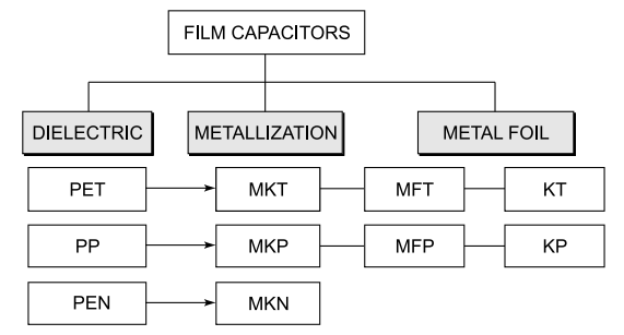
Classification of films capacitors
Short identification codes for the type of construction, describing the dielectric and the basic technology applied, are defined in DIN 41 379.
The last character in the short code indicates the type of dielectric:
T = Polyethylene terephthalate (PET)
P = Polypropylene (PP)
N = Polyethylene naphthalate (PEN)
An M (= metallization) is prefixed for the identification code of capacitors with metallized films, while MF denotes one metallized film and one foil electrode with plain film. Figure indicates the types and nomenclature of capacitors using these films.
Main types of plastic film capacitors
Polypropylene film
Polypropylene has virtually taken over the capacitor scenario in most power frequency AC applications in the past few decades. Its low loss factor, ability to operate up to 100°C, and ease of use have been the deciding factors in this trend. In the 1980s, a search was on for an improved dielectric which could bear more stress and reduce capacitor size.
PP was found to have superior properties in this respect, and in combination with paper, gave better electric strength. Paper capacitors were phased out after the ban on synthetic impregnating oil polychlorinated biphenyls (PCBs), due to ecological factors, and PP was seen as an alternative to be used with paper in mixed dielectric power capacitors.
The very low dissipation factor of PP has made it the only viable material for most high power AC applications. Self-healing properties of MPP in metallized capacitors are critical for reliable high voltage operation.
When an arc-through of the dielectric occurs, PP tends to leave more carbon at the site than polyester. The arc is more quickly extinguished if the gas pressure at the failure site is as high as possible. However, oil impregnation helps improve and make up for this deficiency. Oil acts as a coolant and limits the spark, by conducting the heat away.
Physical sizes of PP capacitors are comparatively higher due to its low dielectric constant. Polypropylene motor starter, motor run, and SCR snubber capacitors are replacing older electrolytic and paper– oil types all of which have much higher dissipation factors.
Polypropylene has virtually replaced paper–oil type capacitors which have much higher dissipation factors. PP is usable in high frequency applications. Larger values and higher voltages, up to 72 μF (and even higher) and 440 V capacitors are common in motor run applications.
Higher voltage ratings have become common in power factor correction capacitors and certain traction capacitors. Its low tan delta and higher service temperature, coupled with the ease of manufacturing film has made it the favoured dielectric among designers.
The capacitance variation over a temperature range is also within 3%, making it stable over the entire usable range. The DC high voltage tolerance of over 650 V per micron reached over the years has helped reduce capacitor dimensions.
Polypropylene is manufactured in two processes – blowing (bubble) and stenter. Initial developments were with the blowing process, which had a limitation of non-uniformity in thickness.
The film was blown into a cylindrical shape and cooled, and then drawn, slit and rolled on machines to get a film. Most PP films today are made with stenter process on machines, which gives it uniform thickness and good mechanical properties. They have good tensile strength in both machining as well as cross direction.
The dielectric constant of 2.22 to 2.25 agrees with most liquid impregnants which were introduced as replacements for PCBs. This was beneficial to ensure a uniform electric field throughout the composite dielectric. In paper/PP/ foil capacitors, a major part of the applied voltage was shared by PP and oil, while paper helped proper impregnation of the dielectric system.
Hazy film
Improvement in capacitor voltage stress necessitated the replacement of paper, which led to the development of hazy film. The film is made rough on one side, or on both sides, which allows the oil to penetrate the capacitor winding volume, and the need for paper has been overcome.
The PP/oil dielectric has very high dielectric strength and matching dielectric constants. This gives the capacitor high uniform electric field stress and reduces the capacitor size. The loss factor and capacitor losses are also considerably lower.
Hazy films from 6 to 17.5 are available today. The thickness of hazy film is not uniform because of serrations and wavy surface, and actual thickness is lower than measured micrometer thickness. The space factor depicts the correction factor to be taken into account while calculating actual film volume and thickness.
It takes into account the effect of air spaces inside the overall film volume. When using hazy film, the space factor needs to be taken into consideration. A space factor of 7–10% is common.
In hazy film, the film surface develops depressions, with a hills and valley structure, which allows the air trapped inside the winding to get a chance to get out through these paths, and the oil fills up these spaces to create a void-free uniform dielectric system.
In some designs, the electrode foil is also shaped on the machine additionally, to intentionally create spaces for this purpose. Given the nature of film and foil, it is very difficult, sometimes impossible, to completely evacuate the air and moisture trapped in the winding.
Hence these extra measures are needed in the manufacturing process, and special provisions are made in winding machines for this purpose. The foil passes over forming rollers to get the serrations or shapes during its flow from take-off spools to winding cores on the machine.
Tnteraction between PP flim and oil
In film/foil capacitors the oil plays an important role. Proper knowledge of this interaction is necessary for perfect impregnation. Capacitor impregnation involves two processes:
- Penetration of oil between layers of PP film and aluminium foil
- Swelling of film due to penetration of oil in the interior of the film
The film partially dissolves into oil and absorbs it. This causes swelling of the film, in turn creating voids in the film, which are filled with oil, increasing its dielectric strength. Absorption of the oil by the film and dissolution of the film into the oil continue until saturation is reached. The time for the entire process depends on temperature.
To ensure full penetration in the winding and complete impregnation, the important parameters are space factor, viscosity of oil, capacitor temperature, oil temperature and vacuum during impregnation.
Polyester films(PET)
PP is being used for both AC and DC applications, whereas PET has its limitations in AC due to its high loss factor. PET has a dielectric constant of 3.2 as against 2.2 for PP, so the size of PET capacitors is smaller in general. The density of PET is 1.35 as against 0.91 of PP, so the weight of PP and PET capacitors is the same for the same thickness.
A PET capacitor is cheaper and in DC, PET has the advantage of smaller size. PET also gives a higher working temperature capability, but when it comes to harmonics or high frequency applications, PP certainly has an edge due to its loss factor and stability over a wider range.
Polyester is probably the most popular dielectric for DC film capacitors. Polyester is a generic term for a class of polymers, the one used in polyester capacitors being polyethylene terephthalate, generally known as PET (Du Pont’s trade name is Mylar).
Low cost, small size and the ability to do many things well enough makes it a good choice for many noncritical applications. A high dissipation factor means it is best used in DC or relatively low-frequency/ low-current pulse and AC power applications. Poor temperature drift, dielectric absorption and leakage limit its use to noncritical analogue circuit applications.
Polyester capacitors can typically be found in values from 0.01 μF to 10 μF and beyond. Polyester has a high temperature drift but can be layered with polypropylene to flatten the temperature curve (the two go in opposite directions). PET capacitors are available to 125ºC.
Good heat resistance allows capacitors to be made in surface-mount styles. Capacitor temperature should not exceed mounting heat resisting temperature during the soldering operation. Polyester has better heat resistance than polypropylene.
PET is tough material and easy to wind, and it does not undergo any stretch related elongation during winding. Very thin films are possible with PET, and films up to 1.5 microns have been made. PP gets stretched at high speeds or under tension, and its thickness can change due to this. Hence it is more difficult to wind, particularly for thin films. PP films are normally used up to 5-micron thicknesses, but nowadays 3.5-micron films have been developed.
Choice of PP/PET for AC applications
All dielectrics have their advantages and shortcomings. For example, polypropylene behaves very uniformly and predictably over temperature and frequency changes allowing suggested operating limits to be calculated and plotted. It has very low dielectric losses. Its voltage tolerance per unit thickness is the highest of all capacitor films.
However, polypropylene has a maximum service temperature limit of +105°C. It also has a low dielectric constant, resulting in a larger physical size for a given capacitance and voltage rating compared with most other film dielectrics. Table compares the properties of these two film types.
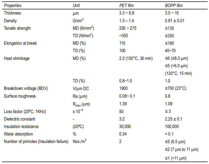
Comparative Properties of BOPP and Polyester
Metallized polyester (and sometimes metallized polypropylene) is lately being used for motor start capacitors, where it is replacing conventional electrolytic capacitors. It draws benefit from the factors below:
- A comparable size of capacitor can be made.
- Its loss factor is extremely low compared with electrolytics.
- It can withstand the AC voltage for a much longer time.
- A smaller value capacitor may therefore be used.
- The motor can be redesigned to allow much higher voltage on capacitor (275 V in placeof 230 V), saving on copper in motor, with consequent saving in cost.
Capacitors made from PP and PET have their own advantages and limitations, as seen from Table below.
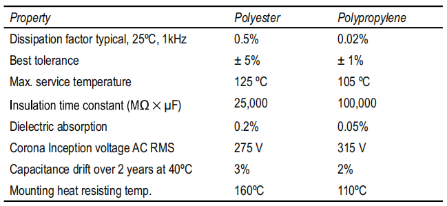
Comparative Properties of PP & PET film capacitors
For metallized polypropylene film capacitors, increase in dissipation factor associated with increasing frequency is due to ohmic losses of lead wires and the metallization alloy deposited on the film. The dielectric losses are very small and do not change. This behaviour allows drawing performance curves that conservatively represent real behaviour in applications.
Figure shows dependence of capacitance on temperature and frequency for PP capacitors. It may be noted that the value of PP capacitor drops by 2% from 25°C to 100°C.
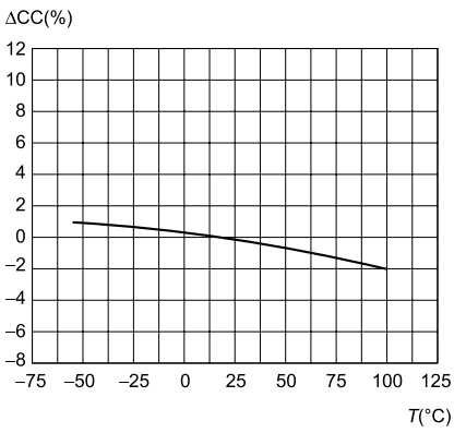
Capacitance variation with temperature
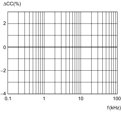
Variation of capacitance frequency
Dependence of PP capacitor value on temperature and frequency
Overall insulation resistance, shown as time constant RC, drops considerably with frequency, whereas the loss tangent remains more or less unaffected up to over 50 kHz .
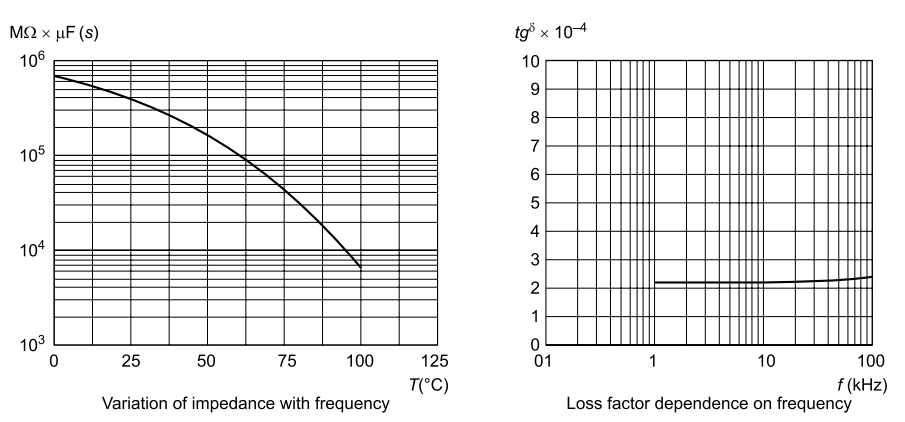
Dependence of impedance and loss factor of PP capacitors on frequency
For metallized polypropylene film capacitors, the increase in dissipation factor associated with increasing frequency is due to the ohmic losses of lead wires and the metallization alloy deposited on the film. The dielectric losses are very small and do not change. This behaviour allows drawing performance curves that conservatively represent real behaviour in applications.
Voltage/frequency capability of polyester film capacitors is particularly more complicated. The reduced size and perceived temperature advantage of metallized polyester film capacitors are strong motivators to consider their use.
Polyester film dielectric losses are usually more than an order of magnitude higher than for polypropylene film, and losses are a very strong function of frequency and temperature. These losses completely dominate over ohmic losses in polyester capacitors. More importantly, the DF behaviour with temperature and frequency cannot be modelled easily.
If the variations of PET capacitors shown in Fig are compared with those of PP capacitors, the PET shows a large variation of capacitance with both temperature as well as frequency. These capacitors therefore do not have a very good stability of value in these respects.
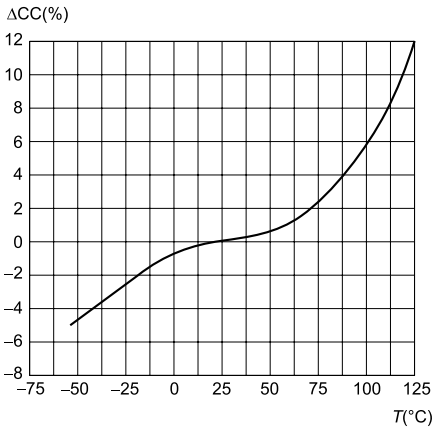
Capacitance variation with temperature
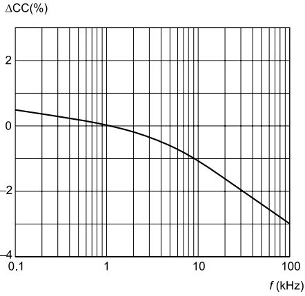
Variation of capacitance frequency
Dependence of PET capacitor value on temperature and frequency
The typical temperature characteristics in Fig show a loss factor vs. temperature graph for polyester film at 1 kHz. Above +50°C the DF starts to climb. For large enough AC voltages the increasing losses with temperature can result in thermal runaway.
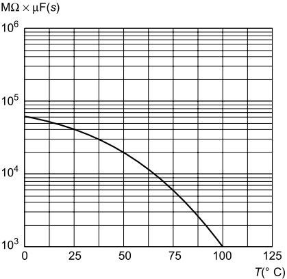
Variation of impedance with frequency
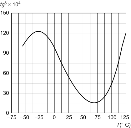
Loss factor dependence on frequency
Typical characteristics of polyester capacitors
It can also be seen that for AC applications, the +125°C internal hot spot temperature limit is extremely misleading. It is very difficult to use the temperature range between + 85°C and + 125°C for AC applications because the allowable AC voltage drops so fast with increasing temperature.
The DF vs. temperature behaviour changes drastically with frequency. The capacitor designer has to conduct the temperature rise tests under the worst electrical and thermal conditions to verify that a proposed polyester capacitor is indeed suitable for that specific application.
Since a very small ambient temperature change can result in a large increase in DF, the polyester capacitor behaviour can be very sensitive to the thermal environment. However, there are many AC applications where polyester capacitors represent the best solution from size, cost and electrical performance options.
Corona discharge and partial discharge
A corona discharge is usually a relatively steady glow or brush discharge in air. The electric field gradient (volts/μm) in air, perpendicular to a dielectric, will be greater than the electric field gradient in the dielectric, by a multiple of the relative dielectric constant unless there is a surface charge on the dielectric.
A corona can be present in air voids in the dielectric at normal working stresses, due to the difference in relative permittivity of air and the dielectric. Operation of the dielectric system in a corona can rapidly cause permanent damage and eventually lead to failure.
However, proper design parameters utilizing an adequate safety factor will allow long operational life of the dielectric system. In a capacitor, discharge may also occur over the film surface at the extreme ends of the winding element over non-metallized surface of dielectric to the end spray or the other side (between two electrodes), if the distance over the surface is insufficient.
The corona inception voltage (CIV) is the lowest AC RMS voltage at which corona discharge occurs as the voltage is increased from zero. CIV is traditionally expressed in the RMS value of a sine wave. Continuous discharge occurs when sinusoidal waves or recurrent transients are applied which are above CIV regardless of the amount of DC voltage component of the applied voltage.
While a corona involves a relatively steady glow in air, partial discharge within a solid insulation system is not visible. An important part of research and development in capacitor reliability has been on the partial discharge phenomenon and its role in capacitor design.
When the voltage across the plates of a capacitor dielectric system is slowly raised, a level is reached where a multitude of partial discharges begin to occur at a consistent voltage level. This is referred to as the partial discharge inception voltage (DIV) of the dielectric system. Partial discharges are very short-duration, minute current pulses that have been observed to occur in dielectric systems under high electrical stresses.
Partial discharge is a localized insulation breakdown of a small portion of solid or liquid insulation under high voltage stress. Voltage stress beyond a limit causes partial breakdown of the dielectric by sparking across air voids in the dielectric, and does not result immediately in complete insulation breakdown.
However, it causes rapid deterioration of the film and/or metallization due to the hot spot temperature resulting from the heat concentrations during the discharge. Presence of impurities lowers the DIV and causes early failure of capacitors.
One must avoid any voids or spaces in capacitor winding which can trap air or moisture. However, even air pockets inside the plastic film created during its manufacturing process will give rise to partial discharges. The result is a continuous electric discharge through these air spaces, causing degradation, partial evaporation of metallization at these points and eventual burning of film. The capacitor will gradually have increased loss factor and will fail.
Corona and partial discharge have the following effects on capacitors:
- Deterioration of dielectric surface at the ends, leading to ultimate failure,
- Bombardment of the dielectric,
- Charring of the dielectric surface by the heat produced by the arc,
- Chemical reaction caused by new compounds such as ozone produced by arc-like conditions.
In case of continuous occurrence, carbon tracks in the dielectric are conductive-cumulative damage may lead to insulation breakdown of film in a relatively short time, and can eventually cause the capacitor to short out and fail.
For film/foil capacitors this will result in a short circuit. For metallized capacitors this will result in removal of the film metallization edges, and thus progressive capacitance loss.
The corona inception voltage is affected by humidity and dielectric thickness. All PP films made for metallization are treated specially to withstand the corona effect.
Comparison of PP and polyester film capacitors
Polyester
[A] Advantages
- High dielectric constant, and available as the thinnest film, resulting in the smallest size for a given capacitance value and rated voltage.
- Lowest cost
- High dielectric strength results in wide operating temperature up to 125ºC
[B] Limitation
- Dissipation factor and capacitance variation with temperature change;
- At higher temperature, the dissipation factor hovers at 1%.
- The capacitance varies about ±5% over the range of -55 to 85℃.
- Capacitance charge from 0 to +50℃ is only ±1%,but beyond this range the variation is very large and rather unpredictable.
- Polyester capacitors are not suitable when close tolerance(≤5%) is needed.
- Power dissipation precludes the use of polyester film capacitors for high current and high frequency AC applications.
[C] Applications
- Ideally suited for electronic circuits for coupling, decoupling and bypass applications.
- Rugged physical and excellent dielectric strength suited for discharge or energy storage application.
Polypropylence
[A] Advantages
- Lower dissipation factor makes it a good choice for high voltage, high-frequency AC, large current applications.
- High insulation resistance, low dielectric absorption makes it ideal for precision DC applications.
- Excellent stability over frequency in KHz range and temperatures up to 105°C.
[B] Limitations
- Lower dielectric constant results in a large size; this is because ultra-thin films are not available in polypropylene.
- Maximum operating temperature: 105ºC.
[C] Applications
- Lower loss makes it a natural choice for AC applications.
- Well suited for high power applications (SMPS).
- Useful in precision applications and when close tolerance is needed (filtering, timing, sample-and-hold, integration).
- Ideal in audio applications.
Polyphenylene sulphide(PPS)
This film is for precision capacitance and wide temperature applications. PPS has replaced PC capacitors in most applications. PPS capacitors are able to operate from –55°C to 150°C and hold capacitance change to less than 1% over the extremes of the range.
Polyphenylene sulphide is the preferred precision-capacitor dielectric and is the dielectric film for modern chip capacitors. Short-term exposure up to 260°C does not degrade capacitors made from PPS. This film is ideal for ‘surface mounting’ or high temperature applications.
PPS capacitors are typically used in timers and filters, and automotive and other applications in high ambient temperatures. PPS applications also include high-frequency coupling, decoupling and general high-speed applications requiring high dv/dt, such as pulse operation in SMPS and snubber applications.
Exposure to both moisture and temperature cycling causes little change. In general, since PPS and PC have the same dielectric constant, the size of a PPS and a PC capacitor will be the same for a given film thickness.
The properties of capacitors made from these dielectrics are summarized in Table below.

Comparative properties of PP、 PET and PPS capacitors