Capacitor dielectrics
Dielectrics are materials that define most of the parameters of capacitors, such as capacitance, loss factor, voltage capacities etc. All dielectrics are insulators. An insulator used between plates or electrodes of capacitor as a supporter of electrostatic field is called a dielectric.
If the flow of current in oppositely charged polarities in an electric field is kept at a minimum, and lines of electrostatic field are not impeded or obstructed, an electrostatic field can store energy. An important property of a dielectric is to cause minimum heat while supporting the electric field. The lower the dielectric loss, the more effective is the dielectric.
In an electric field, atoms of materials undergo orientation of their charge cloud, or its
dipoles from their neutral position . This absorbs certain energy, and the energy is stored so long as the field exists, or even after the field is removed.
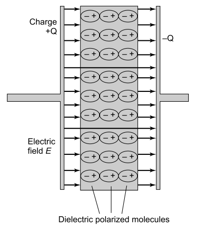
Polarized molecules in electric field.
Once the dipoles are oriented and the external field removed, they do not revert on their own, but must be neutralized externally by some means. No insulator being ideal, there is a leakage current between opposite poles, although this is quite small or miniscule.
The electrons within dielectric molecules are influenced by the electric field, causing the molecules to rotate slightly from their equilibrium positions. The air gap is shown for clarity; in a real capacitor, the dielectric is in direct contact with the plates.
An electric field E is created in the region between the plates that is proportional to the amount of charge that has been moved from one plate to the other. This electric field creates a potential difference V = E*d between the plates of the capacitor.
Most dielectrics are solids, although vacuum and dry air are excellent dielectrics. Some oils and chemicals like transformer oil, petroleum jelly, askarels (poly-chlorinated biphenyls), wax, resins, Phenyl Xylyl Ethane (PXE) Dioctyl Pthalate (DOP), castor oil and some other vegetable oils have been used in composite dielectrics with solids. Some gases also find application in capacitors.
In electrolytic capacitors, an oxide layer is formed on the electrode material as a result of chemical reaction with the electrolyte, and this layer acts as a dielectric. Liquids, when used as insulation in high voltage equipment, have the advantage that any puncture path is self-healing.
They have excellent dielectric properties and high breakdown strength, but these are affected by the presence of impurities and dissolved gases. They are generally used at 50–60 KV/mm, but when used by themselves, can have working stresses of up to 200 KV/mm.
Askarels, a class of poly-chlorinated biphenyls, were the most used liquid impregnants for paper capacitors, but were banned in 1980s due to environmental pollution hazards. Other substitutes like PXE, silicone oils and other synthetic oils, as also certain vegetable origin oils like castor oil and rapeseed oil were developed to take their place.
In composite dielectrics, both components should be inherently stable, and any impurities or pollutants should be scrupulously kept away. They should not react with each other in the presence of an electric field, or thermal and mechanical stress conditions encountered in service or during test conditions.
They should have nearly equal dielectric constants to ensure a uniform electric field. Before the onset of askarels, i.e. prior to the 1950s, transformer oil (dielectric constant 2.2) was being used with kraft paper (dielectric constant 6.0), and voltage stress was limited to 12–13 KV/mm.
Use of askarels (dielectric constant 5.6–6.1) allowed stresses to increase to 17 KV/mm, and subsequently, with improvement in kraft paper, they were further increased to 22 KV/mm.
Dielectrics constant
The dielectric constant may be defined as the ratio of capacitance with a dielectric, to the
capacitance with vacuum as the dielectric in the same geometry. The higher the dielectric constant, the higher is the capacitance in a given geometry, or smaller capacitor volume for a given value.
Vacuum is an ideal material with k = 1, and various materials have values of k ranging from nearly 2 for plastics to 5.8 – 6 for kraft tissue papers, and up to several hundreds or thousands for ceramics and certain oxides. Substances with low k include vacuum, dry air and most pure gases like helium and nitrogen.
Moderate k materials include polypropylene, distilled water, glass, ceramics and paper. Metal oxides in general have high dielectric constants. Table below scans through properties of some dielectrics.
| Dielectric material | Dielectric constant |
| Air | 1.0059 |
| Vacuum | 1.000 |
| Polypropylene | 2.25–2.3 |
| Polyester | 3.2 |
| Pure cellulose or paper | 6.0 |
| Ceramic (COG) | 45 |
| Barium titanate | 1000–30,000 |
| Tantalum pentoxide | 27 |
| Alumina | 10 |
| Glass (Silicon) | 42 |
Dielectric Constants (Relative Permittivity) of Common Dielectrics
A comprehensive list of dielectric properties of a number of materials is given in Appendix A. Dielectrics may be pure materials or composites, with or without liquid/pastes/waxes/jellies. The electrode material can also be from a host of metals or electrolytes, and can take many shapes.
Metals like aluminium, tin, silver, etc. in plate, foil, cylindrical or other formed shapes are in use. The electrodes in modern day capacitors also are in the form of a conducting metallized surface on base dielectric film. Integrated circuits have entire capacitors etched in.
The main asset of high k materials is their small volume but they have low electric strength and high losses compared with electrostatic capacitors. They are not able to stand a high electrostatic field unlike those with lower k. Each dielectric has its own utility in a typical capacitance and voltage range.
Equivalent series resistance(ESR)
Theoretically, an ideal capacitor has an infinite insulation resistance between terminals (as also from the terminal to the case). A real capacitor essentially has both finite series and insulation resistance components.
Series resistance arises out of electrode resistance, wire leads, solder, end connections etc. Insulation resistance (IR) is formed due to dielectric insulation resistance, electrolytes, oils or resins in capacitors, resistance between leads through external atmosphere, between the winding and the case, the case and terminals, resistance of capacitor seals, paints, etc.
Atmospheric moisture and chemicals add their own effects. An additional component is AC resistance when the capacitor is used in AC circuits, due to dipole movements in dielectric material. A high frequency current passing through the capacitor also increases its losses.
The resistive components give rise to equivalent series resistance (ESR), which represents a lumped resistance depiction in series with the capacitor. The overall resistive effect gives rise to the loss factor/dissipation factor/loss angle/tangent of loss angle (tan delta)/power factor of capacitors. (All these terms are used synonymously.)
The ESR is the value of resistance equal to the total effect of a large and complex set of energy loss mechanisms occurring under a particular set of measurement or operating conditions.
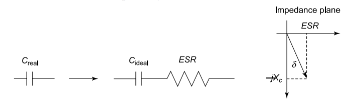
ESR and impedance vector of a practical capacitor.
Q or quality factor of a capacitor is important in tuned circuits because they are more damped and have a broader tuning point as Q goes down. Q = Xc/ESR, where Xc = 1/ ωC = 1/2πfC and ESR is the sum of in-phase AC resistance. It includes the resistance of the dielectric, plate material, electrolytic solution (for electrolytic capacitors) and terminal leads at a particular frequency.
This resistance often is the cause of failures in capacitor circuits due to heat build-up. As the plate area increases, the ESR will go down for the same plate thickness.
Dissipation factor, loss factor, tan delta of capacitor
The dissipation factor (DF) is given as D, or more commonly as tan delta (or tan ). It may be noted that the term D is exactly opposite to Q (reactance/resistance) the quality factor, of an inductor, and the relationship is Q = 1/D.
DF = 1/Q = ESR/Xc
The power factor or loss factor of capacitor is the ratio of real power to apparent power.
Loss factor = I2× ESR/I2Xc = C × ESR = 1/ωC × ESR=1/Q
The loss factor is thus seen to be directly proportional to the frequency of voltage. However, it is often also a function of ambient temperature and biasing voltage as also the voltage stress on dielectric. A good capacitor design also accounts for the resistance introduced by electrode thickness or its shape.
In general, electrolytic capacitors have much higher loss factor compared with other types. Loss factor is given as an absolute per unit quantity, or a percentage of capacitor VA (volt × ampere). For example, it could be written as 0.05, or 5 per cent.
The presence of a resistive component in capacitors gives rise to two components of AC currents – one 90° leading the voltage, and the other in phase with voltage (resistive component), as shown in Fig.
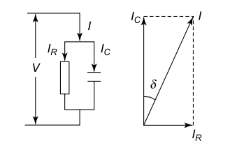
Current components and lose a angle of capacitor.
However, the resistive component in most cases is so small that the total current leads the voltage by almost 90°, deviating only by a small fraction of a degree. Hence the power factor of a capacitor is a very small figure. For this reason, instead of customary power factor angle, its complementary angle is mentioned, the loss angle, whose sine is equal to the cosine of conventional power factor.
At this small angle, its sine is equal to its tangent value, and when the angle is expressed in radians, the tangent is equal to the angle itself. Hence the loss factor is also given as tangent of loss angle, or tanδ (δ being the value of angle in radians).
The loss tangent at any given frequency is the ratio of real and imaginary parts of its impedance. This is an important parameter, and can be vital to the performance of a capacitor as also the circuit where it is used.
In electronic circuits it can give unnecessary resistance, while in an AC circuit it may cause unacceptable heat loss.If we consider a large capacitor of 36 μF working at 440 V 50 Hz AC, with a loss tangent of 0.1 per cent, the watt loss will be roughly 2.2 watts, while the capacitor generates nearly 2200 VA.
For a capacitor unit of 25 KVAR in a power system, the corresponding loss will be 25 watts.Such high losses will cause the capacitors to fail under thermal runaway.
All dielectrics (except vacuum) have two types of losses. One is a conduction loss, representing the flow of actual charge through the dielectric. The other is a dielectric loss due to movement or rotation of atoms or molecules in an alternating electric field. Dielectric losses in water are the reason for food and drink getting hot in a microwave oven.
Most capacitors lose a fraction of the energy when an alternating current is applied. In other words, the dielectric is less than perfect. The simplest model for a capacitor with a lossy dielectric is also represented by a capacitor with a perfect dielectric in parallel with a resistor giving the power dissipation. The current now leads the voltage by a very little less than 90°, where the difference (Greek letter delta) is termed the dielectric loss angle.
The dielectric constant and losses depend on temperature as well as the frequency of applied voltage. This is because the dipole movements cannot keep pace with change in the electric field direction as frequency rises. The dipoles also face higher resistance because of frequency of movements, causing higher heat losses.
The dielectric loss factor represents watt loss in a dielectric material through conduction, slow polarization currents and other dissipative phenomena. Polarization currents occur due to frequent reorientations of dipoles in every half cycle of external AC voltage, as they try to adjust to the rapidly changing electric field.
This oscillation of dipoles involves energy consumption depending upon material properties, and adds to watt loss of capacitor. The loss tangent is a parameter of a dielectric material that quantifies its inherent dissipation of energy. The term refers to the angle in a complex plane between the resistive component of an electric current and its reactive (lossless) component.
Note that the ESR is not simply the resistance that would be measured across a capacitor by an ohmmeter, but is a derived quantity representing the loss due to both the dielectric’s conduction electrons and the bound dipole relaxation phenomena. Table below gives the dissipation factor (tan δ) and ESR of 1 μF capacitor with different dielectrics.
| Dielectric | D. F. (maximum) | ESR for 1 μF capacitor |
| Aluminium electrolytic (50 V) | 10% at 120 Hz | 132.6Ω |
| Tantalum | 4% at 120 Hz | 53Ω |
| Polyester | 1% at 1 kHz | 1.59Ω |
| Polypropylene | 0.1% at 1 kHz | 0.159Ω |
Dissipation Factor and ESR for Common Dielectrics
Most electrolytic capacitors tend to have a high loss factor due to the nature of electrolytes and the dielectric layer characteristics. Their use in AC is therefore very limited, the most common application being motor start capacitors, where a capacitor remains in circuit for just under three seconds, and is switched off once the motor attains speed.
The heat generation can be imagined from the fact that their loss factor can be between 1.8 to 7 per cent, and capacitor values ranges between 40 μF and 300 μF. A capacitor of 200 μF having tanδ of 2% and an applied voltage of 230 V AC will generate 66 W of heating load.
Heat generated in a capacitor must be dissipated from its surface to the environment. This factor has to be built into the design, and sometimes, special measures are necessary for this purpose. Most common methods include use of large containers, providing fins, water-cooled bodies, forced air ventilation etc.
It is common practice to check the heat dissipation surface during design stage of common AC capacitors. Power capacitors on supply systems at substations have to be well ventilated, particularly when used indoors.
Equivalent series inductance(esi)in capacitors
In a wound capacitor, the coil structure leads to the formation of an inductance between leads of capacitors. In such a capacitor, if terminals are brought out from the ends of each electrode foil, an inductance can be measured between these terminal pairs. Further, the coil structure also causes formation of inductance between the two electrodes.
In certain applications like railway carrier line communication networks superimposed on main lines, the inductance of a capacitor winding used to be specified (in μH) between two terminals of each electrode, and played a part in the circuit.
Modern metallized capacitors have their ends sprayed to collect current all through the length and thus have all turns shorted at both electrode ends, making them essentially non-inductive. Extended electrode foil construction in many capacitors also makes them non-inductive.
Leads of capacitors are also a source of inductance. A wire, however small, will present an inductance. If measurements are made at a distance from capacitor ends, they could be slightly different from the one at the ends. The wire length, their shape and gauge affect the value of this inductance.
In small capacitors and at higher frequencies, these inductances could be a nuisance. They may even cause resonance problems at certain frequencies. They need to be compensated/accounted for when dealing with high frequencies or higher order harmonics, and when used for filters.
The equivalent series inductance (ESI) of a capacitor is caused by the inductance of the electrodes and leads. It sets the limiting factor of how well (or fast) a capacitor can decouple noise off a power bus. The ESL (L) of a capacitor also sets the resonance point of a capacitor.
Because the inductance appears in series with the capacitor, they form a tank circuit. At resonance frequency Fr, inductive reactance Xl = ωL becomes equal to capacitive reactance
Xc = 1/2πfC = XL = 2πfL
The resonance frequency is then Fr=(1/2π√LC)
Common dielectric materials
Several materials of different types, varieties and compositions are in use for different types and grades of capacitors. Electrostatic, electrolytic and electrochemical capacitors use dielectrics of different characteristics, and demands on their dielectric layers are different.
Plastic films
Plastic film capacitors are commonly used in modern high-performance electrostatic capacitor applications. Strips of plastic film are wound or stacked between electrodes to serve as dielectrics. Polyester and polypropylene dielectrics are the mainstay of film capacitors.
They are the ones that most film capacitor makers use, although use of polyphenylene sulphide (PPS) is on the rise, replacing polycarbonate film because of its superior properties, along with polyethylene naphthalate (PEN) for a number of applications.
[A] Polyester (PET)
Polyester is probably the most popular of film capacitors. Polyester is a generic term for a class of polymers. The one used in polyester capacitors is polyethylene terephthalate film (DuPont’s Mylar). This is commonly known as PET. Low cost, small size and versatility make it a good choice for most applications.
It has higher dissipation factor, hence it is best used in DC or relatively low-frequency or low-current pulse and AC power applications. Poor temperature drift, dielectric absorption, and leakage currents limit its usage to non-critical circuit applications.
Polyester capacitors can typically be found in values from 0.01 μF through at least 10 μF and beyond. Polyester has a high temperature drift. PET capacitors are available to 125℃. Good heat resistance allows polyester capacitors to be made in surface-mount styles.
PET motor run capacitors and SCR snubbers are replacing older electrolytic capacitors. PET capacitors are the mainstay of most DC capacitors, and voltages up to a maximum of 16 KV DV are available.
[B] Polypropylene (PP)
Polypropylene (PP) capacitors are available in a wide range of sizes and voltages, and are used in a wide variety of circuits. Bi-axially oriented polypropylene film (BOPP) has a very low dissipation factor over its entire temperature range and over a wide frequency spectrum. Dielectric strength is considerably higher than PET or PC film.
This makes polypropylene capacitors popular for high-frequency, high-current applications like switching power supplies. Large capacitors made from PP film, film–oil, and paper–oil–film types are found in power-line applications like power-factor correction. These films can also be used for high voltage capacitors.
Low leakage and low dielectric absorption make small polypropylene capacitors suitable for integrators and sample-and-hold circuits. Moisture absorption is negligible. Only their higher temperature drift makes them inferior to polystyrene. Polypropylene has limited heat resistance (to 105°C), and is not found in surface mount capacitors.
[C] Polystyrene (PS)
Polystyrene (PS), (often called ‘Styroflex’) has long been the material of choice for critical analogue circuits. Low leakage, low dielectric absorption and a flat temperature curve (Fig) makes these capacitors suitable for timing circuits, filters, integrators and sample-and-hold circuits. Moisture absorption is very low.
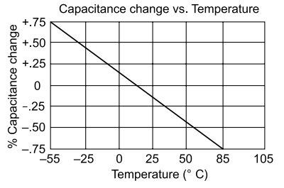
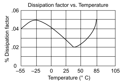
Capacitance and D of PS in relation to temperature
Size, cost, availability and temperature range limitations make polystyrene unsuitable for most other applications. Heat resistance is limited to about 85ºC. It can be damaged by soldering and by chlorinated cleaning solvents.
Because of the poor heat resistance, polystyrene has largely been replaced by polypropylene and C0G ceramics, and the capacitor-grade film is no longer being made. PS’s other electrical properties are mostly very similar to those of PP. Polystyrene has mostly been discontinued from capacitors due to better materials being available.
[D] Poly-carbonate (PC)
Polycarbonate capacitors have been used in a wide variety of applications because of their superior performance. Typically they are used in applications where precision capacitors are needed (<5%). They are generally used in electronics circuits such as filters, as well as for timing and precision coupling applications.
Poly-carbonate capacitors can also be used for AC applications. They are sometimes found in switching power supplies. Although dissipation factor is low, current must be restricted to prevent them from overheating, although they can tolerate temperature better than many other types of capacitor.
Poly-carbonate has a fairly low temperature drift (lower than most films), dissipation factor and dielectric absorption. The poly-carbonate dielectric material is very stable, has a high temperature tolerance and can operate over a temperature range of typically −55ºC to +125ºC without de-rating.
Additionally the insulation resistance and dissipation factors are good and the dielectric constant of 3.0 means that poly-carbonate capacitors are a reasonable size for their capacitance.
It can be used in timing circuits, although ceramics are a better choice for small sizes. It is suitable for some pulse applications, and for some precision analogue applications, especially for good temperature stability and relatively high temperature rating.
The excellent stability of PC capacitors can be seen from Fig, which shows hardly any variation in value and dissipation factor over the full working range. Moisture absorption is high compared to most other film dielectrics, a problem for some critical applications.
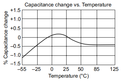
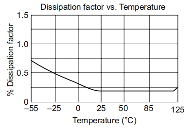
Temperature stability of poly-carbonate film
It has good heat resistance, to 125ºC, but not good enough for in surface-mount packages. It was also being used for automotive applications. This material is becoming obsolete as a dielectric and is being replaced by PPS.
While poly-carbonate capacitors have been widely used within many electronics circuits and found favour with many electronics design engineers, they are not as widely used these days. The Bayer Corporation, the major manufacturer of poly-carbonate, discontinued its production around 2000.
There are still some smaller sources of the dielectric material and some capacitors are still made. However, there are fewer suppliers today, and the film is on the way out from capacitor materials.
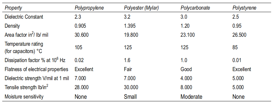
Comparative Properties of PP, PET, PC and PS (Source: Yunstar Electronic Co., Ltd)
[E] Polyphenylene sulphide (PPS)
Like PC, PPS film is available from only one source of supply. Toray (Tokyo, Japan), a film-manufacturing company, makes PPS film trademarked as Torelina. In general, since PPS and PC have the same dielectric constant, the sizes of PPS and PC capacitors will be the same.
PPS has properties closest to PC, and has replaced it in most applications. It is flame resistant, and has good resistance to moisture and solvents. Its cost is comparable to PC, while its dielectric constant is same as PC, and the capacitor size also remains the same.
The ESR performance at room temperature over a frequency range from 100 to 100,000 Hz for polyphenylene sulphide is superior to poly-carbonate. A PPS device may run hotter than a PC device without any problem in some AC applications. PPS, unlike PC, can operate without degradation at capacitor temperatures exceeding the +125°C in DC applications.
Economics is a major consideration in today’s competitive business environment. While the cost of a capacitor depends on many factors, the cost of PPS dielectric film is comparable to the historical cost of PC dielectric film. Furthermore, the supply of PPS has never been interrupted — unlike PC — since the material was first made available as a capacitor dielectric film some 20 years ago.
Dielectric strength of PPS is higher at 400 V compared with 300 V for PC, so film thicknesses could be lower, reducing capacitor size. Capacitance stability is better, with almost a flat characteristic from −55 to 150ºC. Capacitance variation is about only 7 per cent over a wide range of –55 to 85ºC.
The ESR and loss factor are also superior up to about 100ºC. This has become popular for military applications due to the temperature tolerance and relatively smaller sizes. Short-term exposure to 250ºC does not degrade the capacitors.
[F] Polyethylene naphtha-late (PEN)
This is a new film (Teonex from DuPont) dielectric, with electric strength 25% greater than PET. Its working temperature extends to 160–180ºC, has high mechanical strength, good thermal conductivity and lower thermal shrinkage. This permits use of thinner films, and a smaller capacitor size.
Costs of materials and those of capacitors may go down once this is fully commercialized. High temperature characteristics make it ideal for SMD capacitors. Figure brings out the superiority of PPN over PET even at higher temperatures.
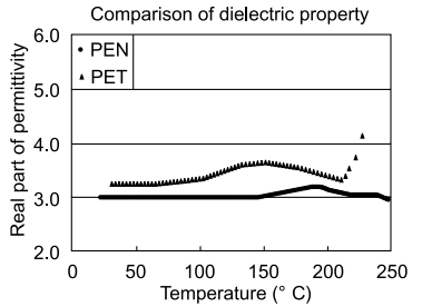
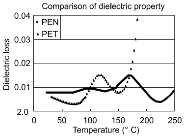
PEN and PET comparison (Source: SKC Inc, Georgia)
PEN is especially suited for the manufacture of chip type capacitors for surface mounting and for increased service temperatures.
[G] Teflon
Teflon TFE is DuPont’s trade name for poly-tetra-fluoro-ethylene or PTFE. It is also sold under a number of other trademarks such as Fluoroplast-4 and Fluon PTPE. PTFE has very low leakage, very low dielectric absorption (probably the lowest in both cases), a very low dissipation factor, a wide temperature range (up to 200ºC for some), low temperature drift, negligible moisture absorption, and very good stability.
It is about the best capacitor film for critical analogue applications. It is expensive, and few companies still make it. The film has exceptionally poor mechanical properties and inconsistent thickness, and manufacturers find it difficult to work with.
PTFE capacitors are available from 0.001 μF to at least 2 μF, but not normally used in SMD. However, a few Teflon SMD parts in very low values, <10 pF are being made.
Teflon is the lowest loss solid dielectric, with operating temperatures up to 250°C, extremely high insulation resistance and good stability. It is used in stringent, mission-critical applications.
Its disadvantages are large size (due to low dielectric constant), and higher cost than other film capacitors. The Teflon film trademark was coined by DuPont and registered in 1945; the first products were sold commercially under the trademark beginning in 1946.
Dielectric constants of all materials depend upon temperature, and the temperature dependence has to be accounted for when selecting a material for an application.
Fig shows the relationship between capacitance and temperature of PP/foil, metallized PP (MPP), metallized PPS (MPPS), metallized PS (MPS), metallized poly-carbonate (MPC) and polystyrene/foil (PS/FOIL) capacitors.
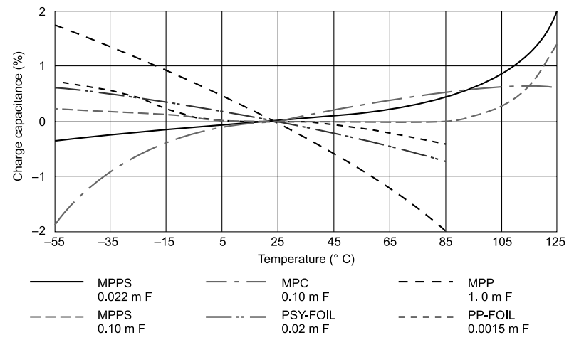
Effect of temperature on dielectric constant of different plastic films.
It will be noted that MPPS capacitors undergo a very small capacitance change from −55°C to +85°C, with maximum variation under 0.5% from their value at 25°C, whereas MPP film capacitors show a reduction in capacitance value up to −2% from 25°C to 85°C. MPC capacitors are most stable between –15°C to 125°C, and practically do not undergo any change from −5 to +85°C.
The dissipation factor (tan ) of most dielectrics goes up with temperature. It can be seen from Fig that 0.1 μF MPPS is the most stable in the whole spectrum up to 100 kHz. Frequency dependence also varies with the size or rating of capacitor for the same film. Width and volume, the aspect ratio (length of winding/winding diameter), the leads and joints in relation to capacitance value are factors which influence capacitor loss.
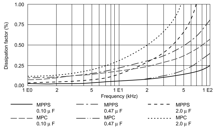
Relationship between frequency and dissipation factor for MPPS and MPC.
Composite dielectrics
Solid dielectrics like kraft paper are porous, and inherently have air and moisture in them. These inhibit the properties of the solid, and need to be removed in order to get full properties as a dielectric. Even film/foil systems will have some air/moisture between layers.
Special films (hazy films) are made, and special processes (vacuum impregnation) are used to remove the air and moisture under high vacuum and temperatures and replace the spaces with a compatible liquid dielectric.
The liquid should have dielectric constant as close to the solid as possible to ensure uniform electric field, and the working voltage stress is dependent solely on the weaker dielectric strength material, which is generally the solid.
Film or paper has to be of very high dielectric strength and must be ideally free from any impurities, conducting paths or pinholes, since each of these reduces the electric strength. The manufacture of films or paper involves rigorous dust and environment controls, and the base material and other items used have to be as pure as practically possible.
However, any film or paper will always unavoidably have certain imperfections, which are inherent or introduced due to manufacturing limitations.
Hence, in capacitors using foil electrodes, paper or PP is generally used in a minimum of two layers, and the number of layers can go up, depending upon the reliability requirements and the voltages used. For example, if the desired thickness is 20 μm, two layers of 10 μm are used.
The chance of weak spots of two layers coming into alignment is very remote and the dielectric can work to its capacity. So the composite film or paper dielectrics generally have two or more layers of base materials, impregnated with a suitable impregnant.
The impregnant may be chemicals, synthetic oils, resins, wax, petroleum jelly, vegetable oil (castor oil and rapeseed oil are common), nitrogen or some inert gas. A choice of impregnants is based on the desired capacitor, its properties, end use and environments of use.
The impregnant has also to be in its purest form and must be processed to remove any impurities and moisture. Flash point and fire point, viscosity and gas contents are also considered. Generally oils are used in most power applications, but waxes and resins are used when it is desired to have a capacitor dielectric system in solid state at a working temperature.
Working voltage stresses of 50–60 KV/mm are common in impregnated film dielectric capacitors, and still higher in metallized capacitors. Impregnants are also used in solid systems to fill the voids in high voltage bushings, where the working stresses can go to 200 KV/mm.
[A] Mixed dielectrics
Often, the dielectrics are used in combination, e.g. PP with paper (with aluminium foil electrode). This allows drawing maximum benefits out of the composite dielectric system. These are impregnated with suitable dielectric oils. Sometimes one of the dielectrics may be a film or paper metallized on one side.
In some other capacitors, paper or PP layer metallized on both sides serves as extended electrode, while the other plain film/paper works as the plain dielectric. This construction is common in power factor capacitors, commutation capacitors or some high frequency applications.
[B] Metallized paper or plastic films
With the development in materials and technology, the search for smaller sizes and better reliability in terms of short circuit failures in service, coupled with economy of design prompted the development of metallized electrodes.
A metal (mostly zinc or aluminium, or an alloy of these) is vacuum-deposited on the film/paper in a thin layer, of the order of 0.03 μm or less in thickness. This does away with 5–8 μm aluminium foil, and the capacitor size is drastically reduced by that much.
The metallization layer is so thin that its current carrying capacity is limited, and current is collected all over the winding length, by spraying of metal on metallized layer ends, and brought out on either side of the winding.
Any short circuit or surge current that may pass through a weak spot creates immense heat at the spot, and the metal around it evaporates. The dielectric is thus rid of the weak spot (which is isolated), and the capacitor continues to operate in the system.
Use of metallized electrode also does away with the necessity to use a minimum two layers of film/paper, as weak spots are isolated during manufacture by a process called ‘Short clearing’. Failures at any weak spot in service are taken care of by self-healing. These advantages have seen the dominance of metallized film capacitors in both electrical and electronic fields in most wound capacitors.
In one type of capacitor construction, kraft capacitor tissue paper metallized on both sides without any side margins is used as electrodes, in place of foil. The capacitor undergoes self-healing on one side of an electrode in case of failure, the second side remaining unaffected.
The decrease in capacitance is less than that in a normal metallized capacitor. The construction is known as MKV capacitor (it was also known as Bosch type capacitors). Metallized electrodes are extended on sides and sprayed with metal to form current collectors.
Electrical properties of the insulating system change due to age and continuous electrical stress. The principal contributor to the unexpected breakdown of the high voltage equipment is insulation failure. As compared to the magnetic, conducting and insulating materials which form the basis of any electrical equipment, the insulating material in a capacitor is more prone to service stresses like thermal stress, electrical stress, mechanical stress, environmental stress etc.
By measuring electrical properties such as capacitance and tan delta periodically,it is possible to ensure an operation free of unexpected breakdowns. The dissipation factor (tan delta) is one of the most powerful offline non-destructive diagnostic tools to monitor the condition of solid insulation of high voltage equipment.
Ceramics
Ceramics are a unique family of dielectrics with dielectric constants ranging from 6 to 10,000. These can be easily manufactured to desired physical and electrical characteristics by applying ceramic chemistry.
For ceramic capacitors, voltage applied to the capacitor also affects its capacitance value (the electric field strength across the dielectric changes the effective dielectric constant k of the material).
Ceramic capacitors are available in three classes. Class I ceramics are used for resonant circuits and high-frequency bypass and coupling. These capacitors have a wider temperature range compared to Class II and Class III capacitors.
Class II ceramics are used where miniaturization is required for bypassing at radio frequencies, filtering and inter-stage coupling. Class III ceramics are used where low-voltage coupling and bypassing in transistor circuits are necessary.
Mica
Mica, a mineral, is one of the oldest dielectric materials used in capacitor construction. There are several kinds of mica, with differing properties, but mica is in general very stable electrically, mechanically and chemically.
There are many types of mica, but only six or so are common rock-forming minerals. Mica capacitors are normally made from muscovite mica, or potassium aluminum silicate, KAl2Si3O10(OH)2 . It is thermally stable up to 500°C, and has a high dielectric strength.
Phlogopite mica, or potassium magnesium silicate, KMg3Si3AlO10(OH)2 , is softer thanmuscovite mica and has less desirable electrical characteristics, but it may be used up to 900°C. India is the biggest supplier of mica.
Mica has a dielectric constant in the range 5–7. Natural mica contains many other materials including iron, sodium, ferric oxide and lithium. Because of the variability in the composition of natural mica, mica destined for use in capacitors must be carefully inspected and classified, which adds to the manufacturing cost.
Although there are several different forms of mica, they all have very similar properties. They are fundamentally very stable both mechanically and chemically, enabling capacitors manufactured with mica to exhibit similar properties.
The crystalline structure of mica has binding forces that are different in different planes. In one plane they are strong, but weak in the perpendicular plane. This gives it a layered structure and enables it to be spilt along the lines of the weak bond into very thin flat sheets. The sheets used in capacitor manufacture are from less than about 0.025 to 0.1 mm.
Mica is very stable and chemically inert. It does not react with oil, water, many acids, alkalis and solvents. As a result of this, ageing does not occur to any major degree, and the variations of water vapour in the atmosphere do not cause undue variations in the overall capacitor performance.
A desired application, size requirements, temperature and environmental conditions decide the choice of capacitor with a particular dielectric. Table compares the properties of some of the most common types of dielectrics.
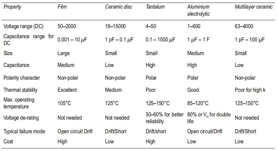
Comparison of Some Common Dielectrics
Glass
Glass is the preferred choice for long-life capacitors, which are highly stable over an entire range of frequencies and temperatures. These are characterized by loss angle as low as 0.0039 even at 1 GHz, and dielectric constant variation from 6.4 at 1 MHz to 6.13 at 1 GHz.
Volume resistivity is of the order of 1014 ohm-cm or higher and surface resistivity of 1013 ohm-cm. Electric strength is also quite high at over 8 KV/mm.
Glass capacitors are used where ultimate performance is required for RF circuits. They offer very high levels of performance, although their cost is high when compared to many other forms of capacitor. Typically a glass capacitor will have a relatively low capacitance value. The values of glass capacitors may range between a fraction of pF up to 3,000 pF. As such these capacitors are used mainly in radio frequency circuit design.
On account of their costs, glass dielectric capacitors are reserved only for the most demanding RF requirements. These are usually low volume products where cost is not as important as in high volume products.
These capacitors are made by only a few manufacturers and the capacitors may not be available ex-stock. Their properties offer real advantages in many applications over all other forms of capacitor. Their combination of robustness and high tolerance sets them above all other capacitors.
When size and cost are not critical, a glass capacitor may solve a problem in a circuit that may otherwise not work properly in the particular environment in which it may need to operate.