What It Does
A variable capacitor allows adjustment of capacitance in much the same way that a potentiometer allows adjustment of resistance.
Large variable capacitors were developed primarily to tune radio receivers, in which they were known as tuning capacitors. Cheaper, simpler, and more reliable substitutes gradually displaced them, beginning in the 1970s. Today, they are still used in semiconductor fabrication, in RF plastic welding equipment, in surgical and dental tools, and in ham radio equipment.
Small trimmer capacitors are widely available and are mostly used to adjust high-frequency circuits. Many of them look almost indistinguishable from trimmer potentiometers.
The schematic symbols commonly used to represent a variable capacitor and a trimmer capacitor are shown in Figure.
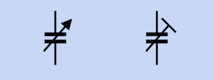
Typical schematic symbols for variable capacitor (left) and trimmer capacitor (right).
A varactor is a form of diode with variable capacitance, controlled by reverse voltage.
How It Works
The traditional form of variable capacitor consists of two rigid semicircular plates separated by an air gap of 1mm to 2mm. To create more capacitance, additional interleaved plates are added to form a stack. One set of plates is known as the rotor, and is mounted on a shaft that can be turned, usually by an externally accessible knob.
The other set of plates, known as the stator, is mounted on the frame of the unit with ceramic insulators. When the sets of plates completely overlap, the capacitance between them is maximized. As the rotor is turned, the sets of plates gradually disengage, and the capacitance diminishes to near zero.
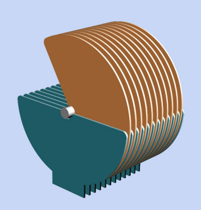
In this simplified view of a variable capacitor, the brown plates constitute the rotor, attached to a central shaft, while the blue plates are the stator. The colors have no electrical significance and are added merely for clarity. The area of overlap between rotor and stator determines the capacitance.
Reduction gears may be used to enable fine tuning of a variable capacitor, which means multiple turns of a knob can produce very small adjustments of the capacitor. At the peak of variable capacitor design, units were manufactured with high mechanical precision and included anti-backlash gears.
These consisted of a pair of equalsized gears mounted flat against each other with a spring between them that attempted to turn the gears in opposite directions from each other. The pair of gears meshed with a single pinion, eliminating the looseness, or backlash, that normally exists when gear teeth interlock.
A vintage capacitor with a spring creating anti-backlash gearing (circled) is shown in Figure . This is a two-gang capacitor—it is divided into two sections, one rated 0 to 35pF, the other rated 0 to 160pF.
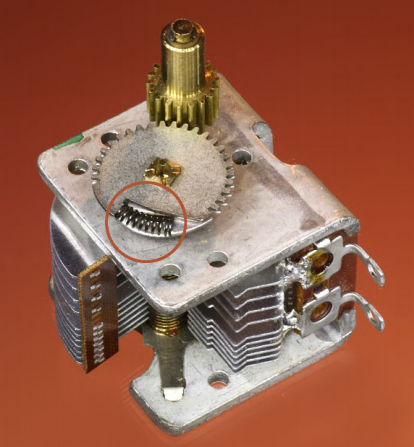
A “traditional style” variable capacitor of the type designed to tune radio frequencies. The spring, circled, enables anti-backlash gearing.
Variants
The traditional variable capacitor, with exposed, air-spaced, rigid, rotating vanes, is becoming hard to find. Small, modern variable capacitors are entirely enclosed, and their plates, or vanes, are not visible.
Some capacitors use a pair of concentric cylinders instead of plates or vanes, with an external thumb screw that moves one cylinder up or down to adjust its overlap with the other. The overlap determines the capacitance.
Trimmer capacitors are available with a variety of dielectrics such as mica, thin slices of ceramic, or plastic.
Values
A large traditional capacitor can be adjusted down to a near-zero value; its maximum will be no greater than 500pF, limited by mechanical factors. A maximum value for a trimmer capacitor is seldom greater than 150pF.
Trimmers may have their values printed on them or may be colorcoded, but there is no universal set of codes. Brown, for example, may indicate either a maximum value around 2pF or 40pF, depending on the manufacturer.
Check datasheets for details. The upper limit of a trimmer’s rated capacitance is usually no less than the rated value, but can often be 50% higher.
Formats
All trimmer capacitors are designed for mounting on circuit boards. Many are surface-mount, with a minority being through-hole. Surfacemount units may be 4mm × 4mm or smaller. Through-hole are typically 5mm × 5mm or larger.
Superficially, trimmer capacitors resemble single-turn trimmer potentiometers with a screw head in the center of a square package. A through-hole example is shown in Figure.
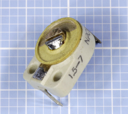
A trimmer capacitor rated 1.5pF to 7.0pF.
How to Use it
A variable capacitor is often used to tune an LC circuit, so called because a coil (with reactance customarily represented by letter L) is wired in parallel with a variable capacitor (represented by letter C). The schematic in Figure shows an imaginary circuit to illustrate the principle. When the switch is flipped upward, it causes a large fixed-value capacitor to be charged from a DC power source.
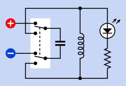
In this imaginary circuit, the capacitor is charged through the double-pole switch in its upper position. When the switch is turned, the capacitor forms an LC (inductance-capacitance) circuit with the coil, and resonates at a frequency determined by their values.
When the switch is flipped down, the capacitor tries to pass current through the coil—but the coil’s reactance blocks the current and converts the energy into a magnetic field. After the capacitor discharges, the magnetic field collapses and converts its energy back into electricity.
This flows back to the capacitor, but with inverted polarity. The cycle now repeats with current flowing in the opposite direction. A low-current LED across the circuit would flash as the voltage oscillates, until the energy is exhausted.
Because the oscillation resembles water sloshing from side to side in a tank, an LC circuit is sometimes referred to as a tank circuit.
In reality, unrealistically large values would be required to make the circuit function as described. This can be deduced from the following formula, where f is the frequency in Hz, L is inductance in Henrys, and C is capacitance in Farads:
f = 1 / (2π * √(L * C) )
For a frequency of 1Hz, a massive coil opposite a very large capacitor of at least 0.1F would be needed.
However, an LC circuit is well-suited to very high frequencies (up to 1,000MHz) by using a very small coil and variable capacitor. The schematic in Figure shows a high-impedance earphone and a diode (right) substituted for the LED and the resistor in the imaginary circuit, while a variable capacitor takes the place of the fixed capacitor.
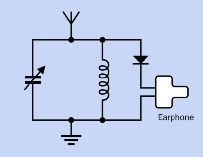
The principle of an LC circuit is used here in a basic circuit that can tune in to a radio station and create barely audible sound through the earphone at right, using only the broadcast signal for power. The variable capacitor adjusts the frequency of the circuit to resonate with the carrier wave of the radio signal.
With the addition of an antenna at the top and a ground wire at the bottom, this LC circuit is now capable of receiving a radio signal, using the signal itself as the source of power. The resonant frequency of the circuit is tuned by the variable capacitor.
The impedance peaks at the resonant frequency, causing other frequences to be rejected by passing them to ground. With suitable refinement and amplification, the basic principle of an LC circuit is used in AM radios and transmitters.
Because variable capacitors are so limited in size, they are unsuitable for most timing circuits.
Trimmer capacitors are typically found in high-power transmitters, cable-TV transponders, cellular base stations, and similar industrial applications.
They can be used to fine-tune the resonant frequency of an oscillator circuit, as shown in
Figure.
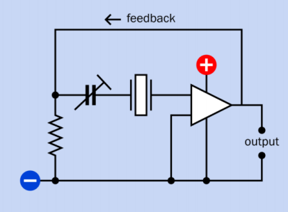
A trimmer capacitor in series with a crystal fine-tunes the frequency of this basic circuit using an opamp.
In addition to tuning a circuit frequency, a trimmer capacitor can be used to compensate for changes in capacitance or inductance in a circuit that are caused by the relocation of wires or rerouting of traces during the development process.
Readjusting a trimmer is easier than swapping fixed-value capacitors. A trimmer may also be used to compensate for capacitance in a circuit that gradually drifts with age.
What Can Go Wrong
- Failure to Ground Trimmer Capacitor While Adjusting it
Although trimmer capacitors are not polarized, the manufacturer may mark one terminal with a plus sign and/or the other with a minus sign. If the capacitor is adjusted while its negative terminal is floating or ungrounded, a metal screwdriver blade will create erroneous readings. Always ground the appropriate side of a trimmer capacitor before fine-tuning it, and preferably use a plastic-bladed screwdriver.
- Application of Overcoat Material or “Lock Paint”
Overcoat material is a rubbery adhesive that may be spread over assembled components to immunize them against moisture or vibration. Lock paint is a dab of paint that prevents a screw adjustment from turning after it has been set. Most manufacturers advise against applying these materials to a trimmer capacitor, because if penetration occurs, the capacitor can fail.
- Lack of Shielding
Variable capacitors should be shielded during use, to protect them from external capacitive effects. Merely holding one’s hand close to a variable capacitor will change its value.